4 Chapter 3: Building Construction
Course Objectives:
- Differentiate among types of building construction. [4.3.12]
- Describe the construction of floors, ceilings, and walls. [4.3.4, 4.3.12]
- Explain how basements and stairs may impact firefighting operations. [4.3.12]
- Compare the construction of different roof types. [4.3.12]
- Describe the construction and operation methods of different types of doors. [4.3.4]
- Describe the construction and operation methods of different types of windows.
There may be structures within your jurisdiction that are hundreds of years old and located next to those constructed in the past year (Figure 3.1). Each will conform to a different building code intended to provide a certain level of fire safety and structural stability. Each will be constructed from the building materials and architectural design common to the construction period. In addition, older structures may have been renovated with engineered lumber or modern insulation systems. You must know the materials used to construct the buildings in your response area, their construction classifications, and the components that make up the structures. You must also know how the building’s design and construction affect fire behaviour and development inside the structure.

Now, what?
Let’s get learning!
Lesson 1
Outcomes:
- Differentiate among types of building construction.
Construction Classifications
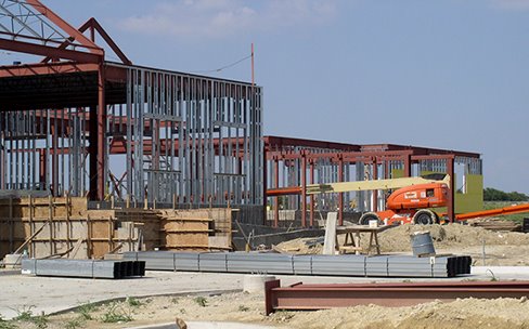
Locally adopted building codes regulate the type of construction based on the intended use (also known as occupancy classification), structure size, and the presence or lack of an automatic fire suppression system. The construction materials and their resistance to fire exposure determine the type of building construction (Figure 3.2).
The authority having jurisdiction (AHJ) adopts and amends building codes to meet local requirements. Some building codes are locally developed although most are based on nationally accepted model building codes. In the United States, there are currently two major model building codes, NFPA 5000, Building Construction and Safety Code®, and the International Code Council’s (ICC) International Building Code® (IBC®). In Canada, to enact building and fire regulations, the provinces, territories, and municipalities pass legislation that references the relevant National Model Construction Codes or provincial codes. The following sections describe the general characteristics of each construction type specified in the model building codes for the U.S. and Canada. While minor differences exist between the model building codes, generally these construction types are common to each. Because local AHJs can amend model codes to meet their needs, you must be familiar with the building codes adopted within your jurisdiction.
United States Construction
Both the NFPA and the IBC® classify buildings in five types of construction (Type I through Type V). Depending on the code and construction type, the types are further divided into subcategories. The construction materials and their performance when exposed to fire define each construction type.
Type I (Fire-Resistive)
Type I construction (also known as fire-resistive construction) provides the highest level of protection from fire spread as well as structural collapse. All structural members are composed of non-combustible or limited-combustible materials with a high fire-resistive rating so that the structural members do not add to the fuel load.

Type I construction can be expected to remain structurally stable longer than other construction types during a fire and is the most collapse resistant. Reinforced concrete, precast concrete, and protected steel frame construction meet the criteria for Type I construction (Figure 3.3).
Type I structures are often incorrectly referred to as being fireproof. While the structure will not burn, the structure may degrade from the effects of fire. Type I construction provides structural stability should a fire occur; however, the addition of combustible materials such as contents, furniture, and interior finishes can generate sufficient heat over time to weaken the building’s structural integrity.
During a fire in a Type I structure, firefighters may experience the following conditions:
- Compartments can retain heat, contributing to the potential for rapid fire development.
- Roofs may be extremely difficult to penetrate for ventilation purposes due to construction materials and design.
- Windows may be non-operating, causing them to be very difficult to open for ventilation.
Key Take Aways – Type I (Fire-Resistive):
- Highest Protection Level
- Offers superior protection against fire spread and structural collapse.
- Structural Composition
- Made of non-combustible or limited-combustible materials with a high fire-resistive rating.
- Stability in Fire
- Remains structurally stable longer than other construction types.
- Materials
- Includes reinforced concrete, precast concrete, and protected steel frames (Figure 3.3).
- Misconception
- Often wrongly considered fireproof; structures are fire-resistant but can degrade under fire conditions.
- Combustible Contents
- Furnishings and interior finishes can still pose a heat threat, weakening structural integrity over time.
- Firefighting Challenges:
- Compartments may trap heat, risking rapid fire development.
- Roofs may resist penetration, complicating ventilation.
- Non-operating windows can hinder ventilation efforts.
** NOTE: Firefighters should remember that while Type I buildings are designed to be the most collapse-resistant, the fire’s heat can still weaken the structure, and interior combustibles can contribute to fire intensity. **

Type II (Noncombustible)
Buildings classified as Type II construction (also known as noncombustible construction) are composed of materials that will not contribute to fire development or spread. Type II construction materials do not meet the stricter requirements of those materials used in the Type I building classification but still do not add to the fuel load (Figure 3.4).
Steel components used in Type II do not need to be protected for the same lengths of time or have the same fire-resistance rating as Type I. The most common form of this construction type includes metal framing members, metal cladding, or concrete-block wall construction and unprotected, open web joists supporting metal roof decks. These buildings are more prone to collapse than Type I, because they are constructed of lighter-weight materials with lower fire-resistance ratings.
Key Takeaways – Type II (Noncombustible):
- Materials
- Composed of materials that do not contribute to fire load or spread.
- Comparison to Type I
- Type II materials are less strict in fire resistance but are still noncombustible (Figure 3.3).
- Steel Components
- Less protection and lower fire-resistance ratings than Type I.
- Common Forms
- Includes metal framing, metal cladding, concrete-block walls, and open web joists supporting metal roof decks.
- Risk of Collapse
- Higher than Type I due to lighter-weight materials with lower fire resistance.

Type III (Ordinary Construction)
Type III construction (also known as ordinary construction) is commonly found in mercantile, business, and residential structures and older schools. This construction type requires that exterior walls and structural members be constructed of noncombustible or limited combustible materials. Interior walls, columns, beams, floors, and roofs are completely or partially constructed of wood (Figure 3.5).
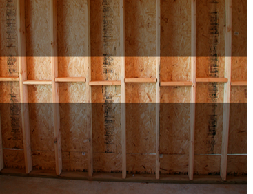
Type III buildings may contain several conditions that can influence fire behaviour, including the following:
- Void spaces inside the wooden channels that roof and truss systems create between wall studs are less protected than in Type I and II construction. Fire will spread through these spaces unless fire stops are installed in the void (Figure 3.6).

Figure 3.7 Fire damaged these trusses resulting in their failure. Courtesy of UL FSRI. - Prefabricated wood truss systems like those used in Type V construction may also be found in new Type III structures. These systems may fail quickly when exposed to fire (Figure 3.7)
Key Takeaways – Type III (Ordinary Construction):
- Common Use
- Found in commercial, business, residential properties, and older schools.
- Exterior Construction
- Non-combustible or limited combustible materials for walls and structural elements.
- Interior Construction
Wood is used for walls, columns, beams, floors, and roofs (refer to Figure 3.6). - Void Spaces
Wooden channels and truss systems create voids that allow fire to spread, unless fire stops are present (see Figure 3.7). - Prefabricated Wood Trusses
- Similar to those in Type V, can be present and may fail rapidly in fire (see Figure 3.7).

Type IV (Heavy Timber)
Type IV construction (also known as heavy timber construction) is characterized by the use of large-dimensioned lumber or laminated wood (Figure 3.8). These dimensions vary depending on the building code in use at the time of construction. The dimensions of all structural elements, including columns, beams, joists, and girders, must adhere to minimum dimension sizing.
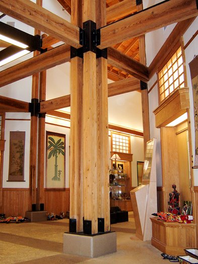
Type IV structures are extremely stable and resistant to collapse due to the sheer mass of their structural members. When involved in a fire, it is the timbers’ own char that reduces heat penetration to the inside of the beam.
Exterior walls are constructed of noncombustible materials. Interior building elements such as floors, walls, and roofs are constructed of solid or laminated wood with no concealed spaces. This lack of voids or concealed spaces helps prevent unseen fire travel.
Modern Type IV construction materials may include small-dimensioned lumber glued together to form a laminated structural element (sometimes called glue-laminated or glulam elements). These elements are extremely strong and are commonly found in churches, auditoriums, and other large facilities with vaulted or curved ceilings. Glue-laminated beams (glulam beams) may fail when exposed to fire because the heat may affect the glue holding the laminates together.
Type IV buildings may contain the following conditions that can affect their behaviour during a fire:
- The high concentration of wood can contribute to the intensity of a fire once it starts.
- Collapse of masonry walls can be caused by loss of structural integrity of timbers.
Key Takeaways Type IV (Heavy Timber):
- Construction Materials
- Utilizes large-dimension lumber or laminated wood (see Figure 3.9).
- Structural Dimensions
- Adheres to minimum sizing for elements like columns, beams, joists, and girders per building code.
- Stability
Highly resistant to collapse due to the mass and size of structural members. - Fire Resistance
- Timber chars in a fire, slowing heat penetration and maintaining structural integrity longer.
- Exterior Walls
- Made of noncombustible materials, aiding in fire containment.
- Interior Elements
- Constructed from solid or laminated wood without concealed spaces, reducing unseen fire travel.
- Modern Materials
- May include glue-laminated elements, especially in buildings with vaulted or curved ceilings like churches or auditoriums.
- Glulam Beams
- Vulnerable to fire as heat may compromise the glue, risking structural failure.
- Fire Behaviour Factors
- Intense fires possible due to high wood concentration.
- Masonry walls may collapse if structural wood integrity is compromised.
Type V (Wood Frame)
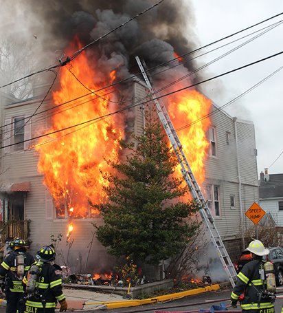
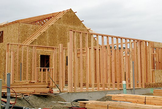
Type V construction is commonly known as wood frame (Figure 3.8). The exterior load-bearing walls are composed entirely of wood.
A veneer of stucco, brick, or stone may be constructed over the wood framing. These veneers offer the appearance of Type III construction but provide little additional fire protection or structural support. Two examples of this type of construction are single-family residences and some multi-story apartment buildings.
Type V construction utilizes wood framing with 2×4 or 2×6 studs, covered by various materials as exterior siding. The siding choice impacts fire spread—some materials can slow it down; others contribute to it. Nails, screws, or glue may be used to attach exterior siding. In the case of stucco, it is spread over a screen lattice that is attached to the framing studs.
Modern materials like vinyl siding, a petroleum-based product, can increase fire load. It generates dense, toxic smoke and melts, exposing flammable insulation or sheathing underneath, potentially accelerating fire spread (Figure 3.10). Increased insulation in some homes is achieved with 6-inch exterior wall cavities or added exterior insulation for energy efficiency.
Type V construction includes the use of a prefabricated wood truss system instead of solid floor joists. This truss system leaves large voids between floors, unlike the closed channel of solid joists. Wood I-beams, typically thin plywood or composite flanked by 2x4s, may have cut-outs for utilities. These are less fire-resistant than solid wood, failing quickly under fire conditions (Figure 3.11).

Key Takeaways – Type V:
- Siding Material
- Affects exterior fire spread.
- Vinyl Siding
- Adds to fire load and produces toxic smoke.
- Insulation
- Enhanced insulation can affect fire behaviour.
- Wood Trusses vs. Solid Joists
- Trusses create voids that influence fire spread and collapse risk.
** NOTE: Important indicators of structural collapse other than construction methods are:
- Size-up
- Duration of fire
- Fireground actions **
Factory-Built Homes
Factory-built homes – also known as manufactured, prefabricated, modular, and industrialized housing – are structures that are partially or completely built in a factory and shipped to the location on which they are to be installed. Factory-built homes take many forms and include mobile homes that have an axle assembly under the frame. Houses may also be constructed from steel shipping containers. Each container is a separate module connected to others to construct a complete house.
Manufactured (Mobile) Homes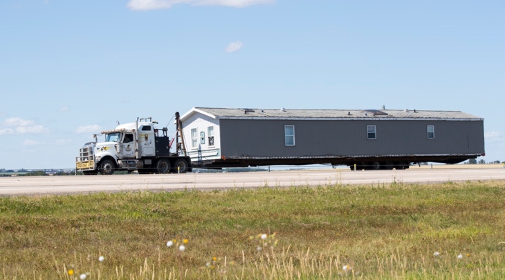
Manufactured homes are the most common type of factory-built homes, almost completely prefabricated before delivery, and the least expensive. Manufactured homes usually have wheels and a permanent steel undercarriage and are towed behind a transport vehicle for delivery.
Construction
Manufactured homes are pre-built and cost-effective, ranging from single to triple-wide, complete with wheels and steel undercarriage for transport.
Regulations
They bypass local codes, adhering instead to HUD standards, which are aligned with Type V construction and favour innovation over traditional model codes.
Fire Resistance
Varies by construction date; post-1976 homes are more resistant due to stricter HUD codes. Older homes with lightweight materials may fail faster in fires but allow easier entry for firefighters.
Design Implications
- Homes may sit on concrete slabs or have ventilating crawl spaces.
- Fewer walls lead to quicker fire spread and potential ventilation issues.
- Rapid spread is possible with adequate ventilation.
Safety Improvements
Post-1980, there’s been a decline in fires, thanks to:
- Factory-installed smoke and CO alarms.
- Flame-retardant materials in interiors and around heat sources.
- Safer appliances.
- Gypsum board instead of wood panelling.
- Sprinkler systems included.
** NOTE: Be aware of the age-related fire resistance of manufactured homes and the influence of their design on fire behaviour. Safety installations in newer models contribute to a decrease in fire incidents and improved outcomes. **
Other Types of Factory-Built Homes
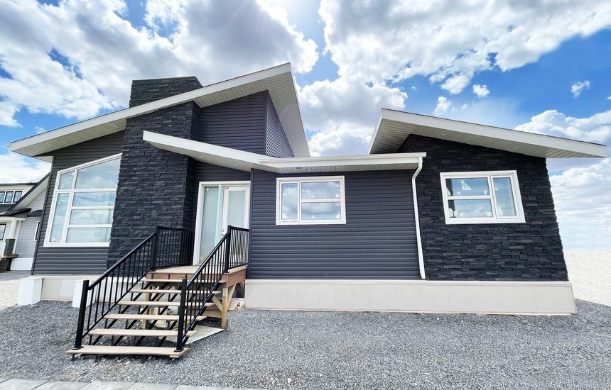 Factory-built homes are constructed in a variety of ways. Based on the method of construction, factory-based homes may be referred to as any of the following:
- Modular homes
Modular or sectional homes must comply with the same local building codes as site-built homes. Only about 6 percent of all factory-built structures are modular homes. Modular sections can be stacked vertically and connected horizontally in numerous ways. The modular section is transported to the site and then attached to a permanent foundation, which may include a full basement. - Panelized homes
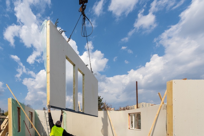 Panelized homes are assembled on-site from pre-constructed panels made of foam insulation sandwiched between sheets of plywood. The individual panels are normally 8 feet (2.5 m) wide by up to 40 feet (12 m) long. The bottom edges of the wall panels are recessed to fit over the foundation sill. Each panel includes wiring chases. Because the panels are self-supporting, framing members are unnecessary.
 - Pre-cut homes
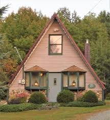
Pre-cut homes consist of individual parts that are custom-cut and must be assembled on-site. Pre-cut homes come in a variety of styles including: - Pole houses
- post-and-beam construction
- Log homes
- A-frames
- Geodesic domes.
- Hybrid modular structure
One of the most recent developments in factory-built homes, the hybrid modular structure includes elements of both the modular design and the panelized design. Modular core units such as bathrooms or mechanical rooms are constructed in the factory, moved to the site, and assembled. Pre-constructed panels are then added to the modules to complete the structure.
Lesson 2
Outcomes:
- Describe the construction of floors, ceilings, and walls.
- Explain how basements and stairs may impact firefighting operations.
Floors, Ceilings, and Walls
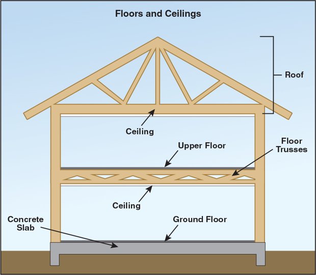
Floors and ceilings form the bottom and top of a compartment with the walls forming the sides (Figure 3.12). Understanding the construction of each can help firefighters understand how these components influence fire behaviour and firefighting within a compartment.
Floors and Ceilings
Floors at ground level may consist of a concrete slab or a floor assembly made up of joists and decking over a crawl space or basement. The upper floors of a multi-story building consist of joists and decking with the ceiling attached to the bottom. The top level of a building consists of a ceiling, joists or rafters and the roof above.
The space between the floor/ceiling or ceiling/roof may contain:
- Duct work or open return air plenum
- Electrical or communications wiring
- Water or natural gas pipes
- Pipes for a fire suppression system
- Recessed lighting and audio speakers
- Fibreglass, cellulose, or foam insulation beneath the roof or under the floor to act as soundproofing.
** NOTE: Some states and local jurisdictions have passed laws and ordinances that require buildings other than single-family dwellings to display a warning placard indicating the type of floor or ceiling truss system used in the structure. If your jurisdiction has this requirement, you must be familiar with it and look for the placards when you respond to a structure fire. **
Floor and ceiling assemblies may be constructed of a combination of materials. Floors may be:
- Poured reinforced concrete
- Cellular concrete over metal decking
- Finished wood, tile, or carpet surface over a wood subfloor attached to metal or wood joists
Ceilings are generally:
- Gypsum board
- Tin tiles
- Lath and plaster attached to joists, roof trusses, or beams
The ceilings in corridors that are designated as exit or egress passageways will have the same fire-resistance rating as the walls in that corridor. The material used to cover the floors in high occupancy structures is also rated to limit flammability in the corridor. Ratings are indicated in hours.
Walls
Walls define the perimeter of the building, as well as divide it into compartments or rooms. Exterior walls may be wood, or metal siding attached to:
- Studs
- A single layer of concrete
- Concrete blocks
- Logs
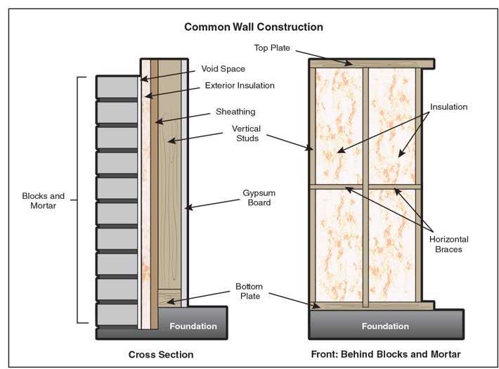
Wall assemblies consist of a bottom plate, top plate, vertical studs, and horizontal braces sandwiched between two surfaces made of gypsum or lath and plaster. The cavity that the two surfaces form may be a void or contain some form of insulation. Insulation may also be installed on the exterior of the wall (Figure 3.13). Firewalls provide separation to meet the requirements of a specified fire-resistance rating.
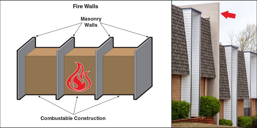
Firewall assemblies include the wall structure, doors, windows, and any other protected openings meeting the required protection-rating criteria. Firewalls may be used to separate two adjoining structures or two occupancy classifications within the same structure to prevent the spread of fire from one to the other. Firewall assemblies can also divide large structures into smaller portions and contain a fire to a particular portion of the structure (Figure 3.14). However, when owners and contractors make unprotected penetrations through these walls for pipes, wires, and ducts, the protection that firewalls provide can be reduced or eliminated. Heat, smoke, and flames can pass through these openings, spreading the fire into compartments that might otherwise have been protected. Exterior walls and firewalls are the most difficult to penetrate when attempting to force entry into an area or to escape an area.
Fire Walls
- Provide separation to meet fire-resistance rating requirements.
- Firewall assemblies include wall structure, doors, windows, protected openings
- May separate adjoining structures or two occupancy classifications in the same structure
- May divide large structures into smaller portions
- Unprotected penetrations can allow heat, smoke, and flames to pass through
- Exterior and firewalls are most difficult to penetrate for forcible entry or escape
Key Takeaways –Walls
- Function of Walls
Define building boundaries and compartmentalize into rooms. - Exterior Wall Materials
Can be wood, metal, concrete, concrete blocks, or logs. - Wall Assembly Structure
Consists of bottom/top plates, vertical studs, horizontal braces, and covering surfaces. - Insulation
May be found within wall cavities or externally on the wall (Figure 3.18). - Firewalls
Special walls that provide a fire-resistance rating to prevent fire spread. - Components of Firewalls
Include doors, windows, and other openings with protective measures. - Impact of Penetrations
Unprotected openings for utilities can negate a firewall’s effectiveness. - Challenges for Firefighters
Exterior and firewalls are difficult to breach for entry or escape.
** NOTE: Firefighters need to be able to recognize the types of walls they may encounter, the potential for fire spread through wall penetrations, and the implications for forced entry and fire containment. **
Basements and Stairs
Basements and stairs present unique challenges for firefighters. Fire in basements can damage floor joists and load-bearing walls that support the upper floor and structure. Stairs can provide a flow path for the movement of air, fire gases, and smoke throughout a structure. Additionally, stairs present a fall danger during low-visibility conditions.
Basements
A basement is a floor of a structure that is either partially or fully below grade level. Single-story basements can also be constructed on shallow foundations. Basements often serve as storage or utility spaces for the structure and house HVAC, breaker box, water heater, and other utility distribution units. Fires in basements may be more hazardous than in other compartments because of limited means of ingress/egress and limited ventilation.
Being partially or fully underground can limit access to the basement. Walk-out or “daylight” basements are part of a structure built on a slope so that one or more sides of the basement may have a door or windows to the exterior. The upper portion of some basements extends above ground level and may have windows around the above-ground perimeter to allow light into the basement. Some basements are only accessible through interior stairwells; others have both interior and exterior stairs (Figure 3.15).
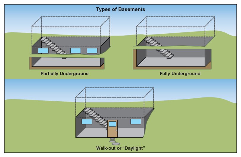
Basements may be unfinished, lacking drywall on exposed wall studs and ceiling joists. The absence of drywall reduces the fire resistance of the studs and joists making the structural members part of the fuel load in the space. If these members fail, the floor above will collapse into the basement.
Stairs
Stairs provide access to, or egress from, different levels of a structure. Stairs in commercial and multifamily residential buildings that are a part of the required means of egress must provide protection for the occupants as they travel to safety. Stairs meeting these requirements are called protected or enclosed because they are built to resist the spread of fire and smoke.
Stairs that are not required to be a part of the means of egress system and typically connect no more than two levels are called access or convenience stairs. Stairs can be classified as either interior or exterior stairs, depending on their location.
The design or layout of a set of stairs may take any of several different forms. Although exterior fire escapes, escalators and fixed ladders have been used as a means of egress in the past, they are no longer allowed as a required means of egress from normally occupied spaces.
Protected Stairs
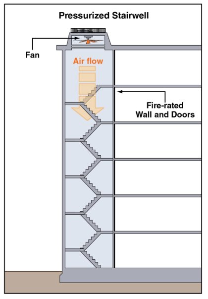
Interior protected stairs are critical components of the life safety system of a building. Protected stairs are enclosed with fire-rated construction, usually with either a 1- or 2-hour rating, depending on building height. Protected stairs generally serve two stories or more and are part of the required means of egress. They are the primary egress paths from floors above or below ground level and can adversely affect the safety of occupants if they do not maintain a breathable atmosphere. Firefighters should control the doors on protected stairs to maintain the integrity of the stairwell.
Sometimes securing stairway doors open may facilitate either ventilation of the structure or evacuation of occupants. Only secure the doors in the open position when doing so will not endanger occupants or firefighters using the stairwell. High-rise structures may have pressurization or other methods for protecting stairwells that will fail if doors are left open (Figure 3.16).
Protected Stairs
- Critical component of building’s life safety system
- Enclosed with fire-rated construction, usually a 1- or 2-hour rating
- Generally, serve two stories or more
- Generally, part of the required means of egress
- Primary egress paths for floors above or below ground level
- Can affect safety of occupants if they do not maintain breathable atmosphere
Exterior Stairs
Exterior stairs may be either open to the air or enclosed (Figure 3.17). Enclosed exterior stairs must comply with requirements similar to those of interior protected stairs. Open stairs are naturally ventilated but may be partially enclosed from the weather. They typically have at least two adjacent sides open to natural ventilation.
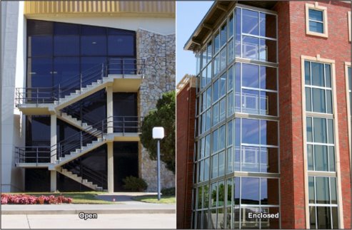
Enclosed stairs
- Must comply with requirement; similar to interior protected stairs
Open stairs
- Naturally ventilated
- May be partially enclosed
- Typically have at least two adjacent sides open to natural ventilation

Unprotected Stairs

Because unprotected stairs are not enclosed with fire-rated construction, they may serve as a flow path for fire and smoke. They will not protect anyone using them from exposure to the products of combustion. Building codes typically allow the use of unprotected stairs in buildings when they connect only two adjacent floors above the basement level (Figure 3.18).
Unprotected Stairs
- Not enclosed with fire-rated construction
- May serve as flow path
- Will not protect anyone from exposure to products of combustion
- Typically allowed only to connect two adjacent floors above the basement level
Test Your Knowledge!
Lesson 3
Outcomes:
- Compare the construction of different roof types.

Roofs
The primary function of the roof is to protect the structure and its contents from the effects of weather. The shape and construction of the roof are intended to provide drainage, support the weight of accumulations of snow, and resist the effects of wind. Therefore, the geographic location of the structure can influence the type and construction of the roof. Penetrations or openings in the roof are indications of the general arrangement of the rooms within and may be used to assist in vertical ventilation during a fire.
**NOTE: Building owners or occupants may make unapproved or non-permitted modifications to roofs during construction or renovation.**
Roof Types
In general, you will encounter three prevalent types of roof shapes: flat, pitched, and arched. Some buildings have a combination of these roof designs. Some of the more common styles that compose these types are:
- Pitched
- Gambrel
- Mansard
- Sawtooth
- Hip
- Shed
- Lantern
- Butterfly
Less common styles are sawtooth and butterfly roofs. Residential structures may have a combination of these styles which can contribute to voids underneath and limit the ability of firefighters to access areas under the roof. Figure 3.19 illustrates the various styles of roofs commonly found in North America.
Flat Roofs
Flat roofs are commonly found on commercial, industrial, and multifamily residential structures, as well as on some single-family residences. Flat roofs generally have a slight slope to facilitate drainage. Chimneys, vent pipes, shafts, scuttles, and skylights are common features that penetrate through flat roofs. Parapet walls may surround flat roofs. Fire separation walls may divide the roof from neighbouring roofs. These firewalls extend from the foundation to above the roof. Obstructions that may also be located on roofs include:
- Water tanks
- Antennas
- Signs
- HVAC equipment
- Solar panels
Pitched Roofs
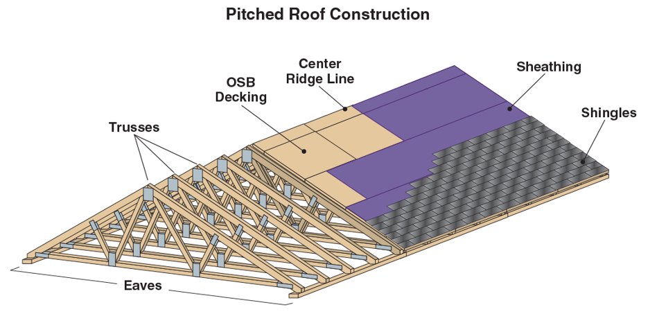
There are several pitched roof styles. Among the most common are those elevated in the centre along a ridge line with a roof deck that slopes down to the eaves along the roof edges. Shed roofs are pitched along one edge and the deck slopes down to the eaves at the opposite edge. Most pitched-roof construction involves beams or trusses that run from the ridge line to the top of the outer wall at the eaves level. These beams or trusses can be made of wood or metal. The roof decking or sheathing material, usually plywood or oriented strand board (OSB), is applied at right angles over these beams, sometimes over the entire roof. In other applications, decking consists of boards or planks set with a small space between them. This is commonly called skip sheathing. Pitched roofs usually have a covering of roofing paper applied before the finish surface is laid . The finish may consist of the following:
- Wood or asphalt shingles
- Asphalt roll roofing
- Metal panels
- Slate
- Tile
Flat Roofs:
- Common in: Commercial, industrial, multi-family residential, some single-family homes.
- Design: Slight slope for water drainage.
- Features: May have chimneys, vent pipes, shafts, scuttles, skylights, and parapet walls.
- Firewalls: Extend from foundation to above the roof for fire separation.
- Roof Obstructions: Include water tanks, antennas, signs, HVAC units, and solar panels.
Pitched Roofs:
- Varieties: Ridge line elevated styles, shed roofs sloping to one edge.
- Construction: Beams or trusses made of wood or metal from ridge line to eaves.
- Decking: Plywood or OSB, applied over beams, sometimes with skip sheathing.
- Roofing Layers: Include roofing paper under the final surface (Figure 3.20).
- Finishes: Wood or asphalt shingles, roll roofing, metal panels, slate, or tile.

Arched Roofs
Arched roofs are ideal for some types of occupancies because they can span large open areas unsupported by columns, pillars, or posts. Arched roofs were primarily constructed from the late 1800s to the mid-1900s due to the availability of inexpensive lumber. The design of an arched roof depends primarily on the exterior walls to support the weight of the roof. Types of arched roofs include ribbed, pleated barrel, diagonal grid (Lamella) and bowstring as illustrated in Figure 3.21.
Roof Construction
Roofs are made up of three main components including the roof supporting structure, the roof deck or sheathing, and the roof covering. On some types of structures, such as single-family residences, the roof covering is the most visible component when viewed from the outside. On other types of structures, a view of the entire roof may be obstructed by the height of the building, parapet walls, or adjacent buildings. When viewed from inside, the roof supports and deck may be visible or covered by a ceiling assembly which creates a void that may be a few inches (millimetres) or many feet (meters) in depth.
Roof Supports
There are two general types of roof supports used in residential and commercial construction: beams and truss assemblies.
Beams: The sections of lumber located directly under the roof decking.
- On pitched roofs, they extend from the ridge line or pole at the peak to each side wall.
- On flat roofs, the beam extends from wall to wall.
- The beam may be exposed or concealed behind a ceiling.
- Box beams and I-beams: aka wide flange beams,
- Manufactured from plywood and are often used in conjunction with wood joists to support flat roofs and floors.
- Provide adequate structural strength under normal conditions, but the thin web portion of plywood I-beams makes them susceptible to early failure in a fire.


Roof truss assemblies
Triangular-shaped assemblies of (usually) two-by-four lumber held together with steel gusset plates.
- May be conventional framing constructed on-site or pre-manufactured in a factory and shipped to the site (Figure 3.22).
- Trusses constructed on-site take longer to build and consist of top and bottom chords and webbing that extend from the peak to the walls. A horizontal joist with supports between the joist and the rafters connects the ends.
- Wood trusses are assembled using metal gusset plates (gang nails) that only penetrate about 3⁄8 inch (9.5 mm) into the wood.
- As wood burns away from the plates during a fire, the plates fall out and are no longer a structural support for the truss (Figure 3.23).
- Trusses created from engineered materials are also susceptible to early failure.
- The open web design of truss joists permits the rapid spread of fire in directions perpendicular to the truss joist instead of simply along the long dimension of the member.
- Truss types include:
- Parallel chords – constructed of wood or metal, are generally used to support flat roofs and floor assemblies.
- Pitched chords
- Arched chords – not to be confused with bowstring trusses (Figure 3.24).

Engineered construction systems
Manufactured from smaller pieces of wood or light gauge steel to form trusses that weigh less than traditional systems made from solid wood or heavy gauge steel. Lightweight construction is becoming more common, and other than Type I and Type IV construction, it can be found in: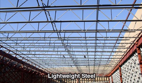
- Homes
- Apartments
- Small commercial buildings
- Warehouses
Two of the most common types of engineered construction systems involve the use of lightweight steel or wooden trusses.
Lightweight steel trusses
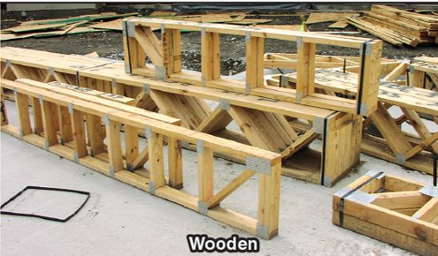
Made from long steel chords that are either straight or bent up to 90 degrees with eitherflat or tubular members in the web space (Figure 3.30).
- Flat roofs are supported by open-web steel joists and steel beams. Depending on the fuel load within the structure, unprotected lightweight open-web joists can be expected to fail quickly in a fire.
Roof Decks
The roof deck is the portion of roof between the roof supports and the roof covering.
Types of roof decks found in North America include:
-
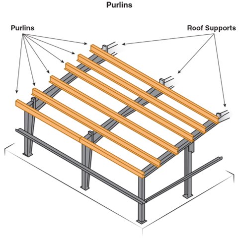
Figure 3.26 Purlins are horizontal members that are attached to roof supports. Plywood sheathing
- Oriented strand board (OSB)
- Wood tongue and groove
- Corrugated metal
- Sprayable concrete encapsulated polystyrene
- Reinforced concrete
- Double tee preformed concrete
The components of roof decks include sheathing, roof planks or slabs, and purlins (Figure 3.26). Sometimes, as in concrete deck roofs, the roof deck serves as the roof support, in other cases, they are the same. Corrugated steel decking is frequently used in applications where it serves as both the deck and the exterior roof covering.
If a multi-story building is to have a flat roof, the usual practice is to use the same structural system for the roof and the floors because it is more economical. Therefore, a building with wood-joisted floors usually will have a wood-joisted roof system and a steel-framed building will have a steel roof. It is possible to encounter exceptions to this rule: i.e. a story has been added to an older building.
There are two basic types of concrete roofs common in North America:
- Cast-in-Place
- Pre-cast
Cast-in-place
Concrete is placed into forms at the building site as a wet mass and hardens in prepared forms. This permits the designer to cast the concrete in a wide variety of shapes. This type of concrete roof does not develop its design strength until after it has been placed in the location where it will be used.
Precast
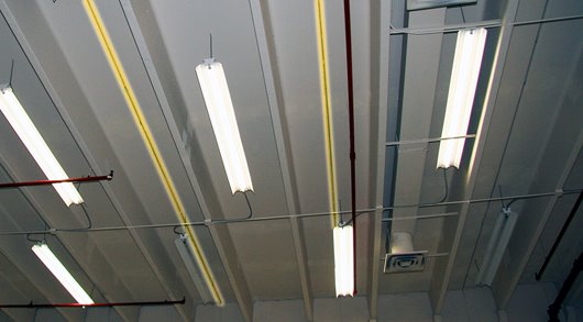
Lightweight concrete roofs
A particular variation of precast construction. These roofs have gypsum plaster and Portland cement mixed with aggregates, such as perlite, vermiculite, or sand to form lightweight concrete.
- Lightweight, precast planks are manufactured from this material, and the slabs are reinforced with steel mesh or rods.
- Time, corrosion, moisture, or exposure to heat may cause concrete to separate from metal reinforcement and degrade its structural integrity.
- Lightweight concrete roofs are usually finished with roofing felt and hot tar to make them watertight.
- These roofs are extremely difficult to penetrate when performing vertical ventilation.
Roof Coverings
The roof covering is the part of the roof exposed to the weather. Roof-covering materials include (Figure 3.28):
- Shingles
- Asphalt
- Wooden or shake
- Fiberglass
- Rubber
- Solar
- Tiles
- Terracotta
- Concrete
- Slate
- Synthetic membrane
- Blown-on foamBuilt-up tar and gravel surface
- Metal roof systems or sheets
- Composite materials
- Asphalt sheets
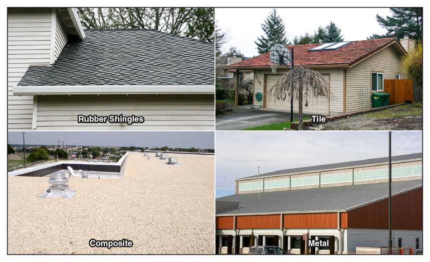
Figure 3.28 Roof coverings may include rubber shingles, terracotta tiles, and composite and metal materials. Test Your Knowledge!
Roof Penetrations and Openings
Roof penetrations and openings include items that provide light, ventilation, access, vapour exhausts, or are part of the plumbing or HVAC systems. Roof openings may be locked or secured in some manner. Roof penetrations and openings include (Figure 3.34):
- Scuttle hatches
- Skylights
- Monitors
- Automatic smoke vents
- Ventilation shafts
- Ventilation fans
- Penthouse or bulkhead doors
- Chimneys
- HVAC exhausts
- Bathroom vent pipes
- Attic vents
- Dormers

Figure 3. 34
Penetrations can indicate the location of some types of rooms such as bathrooms or mechanical spaces. Monitors, smoke and attic vents, scuttle hatches, and skylights may be used to gain access to attics and cocklofts and may be used to provide an exit point for some types of ventilation.
Roof Modifications
Roof modifications should be identified during preincident surveys, the initial size-up, and at other times in case the structure needs to be ventilated.
Roof modifications include:
- Green roofs
- Cold roofs
- Photovoltaic roofs
- Rain or snow roofs
- Security
- Structural modifications
- Roof-mounted equipment
Green Roofs System
Definition
Roofs used for gardens, adding a ‘dead load’ to the structure.
Load Considerations
Ranges from 20 to 150 pounds per square foot.
Construction Impact
Must be supported by structural design in new buildings or assessed in existing structures.
Firefighting Challenges
Under fire conditions, the increased load can accelerate structural failure, particularly if the roof is combustible. They can also interfere with ventilation practices and fire location indicators. Other concerns include:
- The effects of high-velocity winds and uplift wind pressures
- Roof drainage, which can add weight to the roof creating a collapse hazard
- The exposure hazard that dry vegetation on the roof may create
- The need for a clear space between vegetation and firewalls that penetrate the roof
Cold Roof System
Purpose
Designed to prevent ice damming in cold climates by keeping the roof surface cold.
Structure
Includes a sheathing layer, a condensation-preventing membrane (like Tyvek®), and two parallel spacers (two layers of 1 x 4-inch) creating an insulating air void (3-inch), topped with a second sheathing layer, and the roof covering system.
Firefighting Note
These roofs create significant difficulty for firefighters during vertical ventilation operations due to their multi-layered construction.

Photovoltaic (PV) System (Solar Energy)
Function
Generate renewable energy via solar panels on or integrated into the roof.
Location
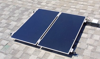
Photovoltaic cell panels can be laid on top of a roof or embedded in the roof (Figure 3.30)
Significant Hazard
Even if power to the building is shut off, the panels retain a significant amount of electricity. If light is available – even light from fire apparatus headlights or lighting equipment – the panels will continue to produce power. Panels will continue to produce electricity even if they are fire-damaged.
Safety Precautions
- Avoid breaking photovoltaic cells or solar-powered skylights as they will remain energized.
- Solar panels may not be visible from the ground on a building with a flat roof.
- The panels also present a significant tripping and falling hazard.
** NOTE: Due to the hazards these systems present, it is crucial that fire departments identify their presence during pre-incident planning. **

Rain or Snow Roofs
Rain roofs, also called snow roofs, may be found on commercial buildings, schools, and residential structures. These assemblies are pitched roofs built over older flat roofs for:
- Aesthetic purposes
- Leak prevention
- Directing moisture off the roof
- An alternative to repairing or resurfacing the original roof
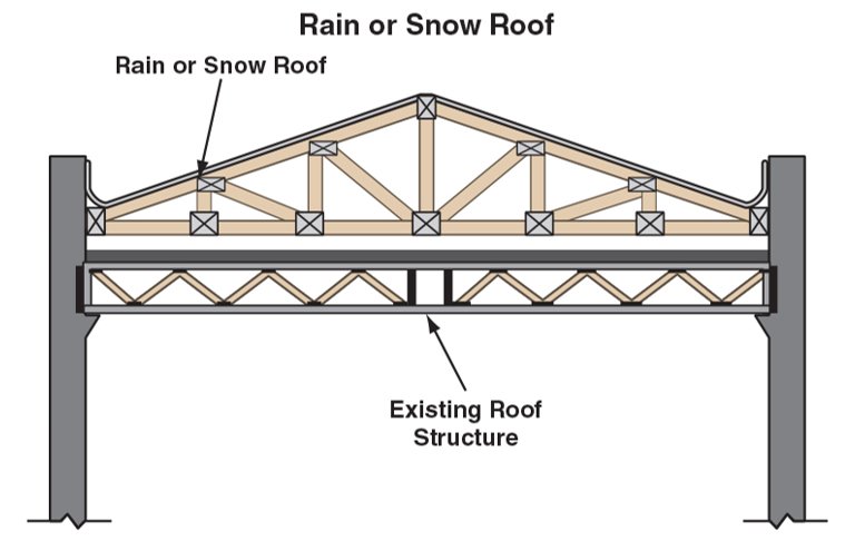
Rain roofs are also built over mobile homes to provide a more permanent appearance. They may be constructed from lightweight metal panels and trusses to form a peak or simply a second flat roof surface made from wood and roofing materials. The void that the rain roof creates can conceal a fire and allow it to burn undetected (Figure 3.31). As trusses are exposed to fire, they weaken, increasing the potential for the collapse of both the rain roof and the original roof. HVAC units may also be hidden from view under the rain roofs, adding to the collapse potential.
Ventilating a rain roof will not remove smoke from within the structure until the original roof is penetrated.
Firefighters should not enter the void area to cut a hole in the original roof because they can:
- Become trapped in the void.
- Be overcome by the heat and smoke trapped in the void.
- Fall through a weakened original roof.
- Be caught in an extreme fire condition as the heated gases mix with fresh air.
Roof Security
Wired glass may be installed for security purposes in rooftop skylights. This type of glass is difficult to penetrate and takes time to remove. Firefighters may encounter other types of roof security. For example, store owners may install iron plates on the roof of a grocery store to prevent break-ins. During a subsequent fire, the weight of the plates can cause the roof to collapse. Installations like this can also prevent timely tactical vertical ventilation. Thorough preincident surveys should uncover barriers like these.![]()
Roof-Mounted Equipment
Most commercial, industrial, institutional, educational, and some residential structures have equipment mounted on the roofs, especially on flat roofs. These items add to the load distributed on the roof, increase collapse hazards, and add to the obstructions that can affect ventilation efforts. Some items may also be found on flat roofs underneath rain roofs.
Roof-mounted equipment includes (Figure 3.32):
- HVAC units
- Water towers
- Telecommunications equipment
- Telephone towers
- Radio transmission equipment
- Television antennas and satellite dishes
- Advertising signs or billboards
- Recreation areas
- Wind generators
- Electrical transformers
- Derricks, hoists, and cranes
- Winches
- Steeples, minarets, spires, and crosses
- Electrical lines and weather heads
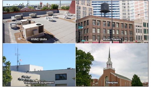
Figure 3.32 Examples of equipment that may be mounted to a roof. Rooftop water tank photo courtesy of Don Turno.
Many firefighters have been injured and killed because roof-mounted equipment has caused the collapse of a fire-weakened roof. Being aware of fire behaviour and how it affects a building as well as the general design and construction of the fire building can help keep you safe.
Key Takeaways – Roof-Mounted Equipment
- Found on roofs of most commercial, industrial, educational and some residential structures.
- Add to load distributed on the roof
- Increase collapse hazards
- Obstructions that can affect ventilation
- May be underneath rain roofs
- Many firefighters were killed and injured because of roof-mounted equipment causing roof collapse
- Be aware of fire behaviour, how it affects a building, and the general design and construction of the building.
Test your Knowledge!
Lesson 4
Outcomes:
- Describe the construction and operation methods of different types of doors.
- Describe the construction and operation methods of different types of windows.
Doors
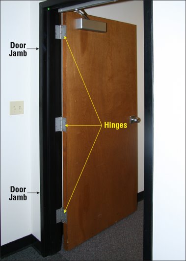
Doors play a critical role in fire control and managing flow paths. Doors are generally classified by the way that they operate. The following types of doors are commonly used in modern building construction:
- Swinging
- Sliding
- Folding
- Vertical
- Revolving
Doors are typically made of materials like wood, metal, and glass, each affecting their fire resistance and how they may be forced during emergencies.
Swinging Doors
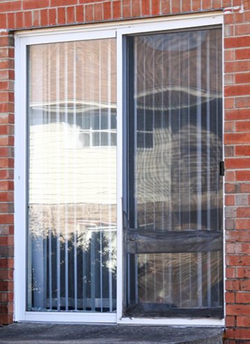
Mechanism: Rotate on hinges or pivot posts (Figure 3.33).
Variants: Can be single or double-leaf, single-acting (swinging in one direction), or double-acting (swinging in two directions)
Usage: Commonly used as required exit doors for egress.
Sliding Doors
Design: Hang from overhead tracks, often with floor guides to prevent lateral movement (Figure 3.34).
Types: Include surface, pocket, and bypass sliding.
Application: Useful for space efficiency; pocket doors hide away when open, commonly used in homes.
Limitation: Not permitted as part of a means of egress in emergencies due to their potential to impede quick exit.
Folding Doors
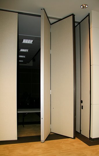
Design: Attached to an overhead track, using rollers or glides.
Types: Bi-folding or multi-folding.
Applications: Found in residential settings, to subdivide spaces into assembly areas and as horizontal fire doors (Figure 3.35).
Fire Safety: Horizontal fire door assemblies must comply with safety standards and be certified for egress purposes.
Vertical Doors
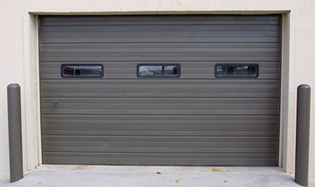
Definition: Known as overhead doors, these open vertically and are common in industrial settings.
Applications: Include loading dock doors, garage doors, freight elevator doors, and fire doors (Figure 3.36).
Structure: May be a single leaf or multiple horizontal panels.Operation: Equipped with counterbalances like weights or springs for ease of use and can be operated manually or by power.
Revolving Doors
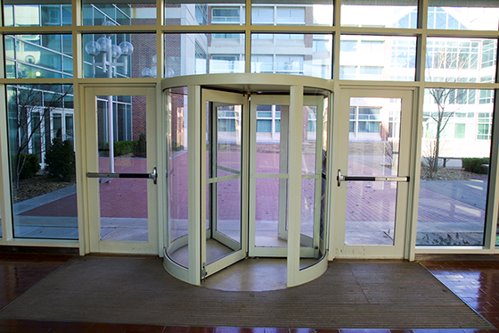
- Structure: Consists of three or four rotating wings within a circular frame (Figure 3.37).
- Purpose: Designed to reduce air exchange and maintain interior temperature.
- Fire Situation Challenges: Can impede hose and equipment entry and are slower for crowd egress compared to swinging doors.
- Safety Feature: Wings collapse under pressure to allow an unobstructed exit with different mechanisms for older and newer models, including chain keepers and spring-loaded hardware.
Wood Panel and Flush Doors
Wood Panel Doors: Feature vertical and horizontal framing filled with wood, glass, or louvres (Figure 3.38).
Flush Doors (slab doors): Have flat face panels, that are the full height and width of the door, covering a solid or hollow core. Sometimes designed with openings for glass vision panels or ventilation louvres.
Construction Evolution: Modern flush doors are smooth on both sides, often made with a wood core and plywood layers.

Solid-Core Doors:
- Built with a dense interior core of laminated blocks of wood, particleboard, or a mineral Composition for stability.
- The core is covered with two or three layers of surface material, which is usually plywood.
- If a wood solid-core door is intended for exterior application where security is a concern, a layer of sheet metal may be attached to the exterior surface. This added layer makes forcing the door more difficult.
Hollow-Core Doors:
- Constructed with a wood, plastic, or fiberboard honeycomb grid between face panels for support.
- Lighter and more cost-effective than solid-core doors but offers minimal insulation.
- Typically used for interior applications due to their insulating limitations.
Solid-core doors are better fire barriers than either panel doors or hollow-core doors. A solid-core door that has not been specifically designed as a fire door will act as a significant barrier to fire if it is closed at the time of the fire.

Glass Doors
Usage: Common in office and retail buildings, suitable for both exterior and interior.
Types: Can be framed or frameless (see Figure 3.39).
Construction:
- Frameless doors are a single glass sheet with attached hardware.
- Framed doors have glass set within metal or wood frames.
Safety Standards: Building codes mandate the use of tempered glass for durability. Plastics like Lexan® or Plexiglas® may be incorporated for added security.

Metal Doors
Common Design: Hollow doors crafted from steel or aluminum (Figure 3.40).
Dimensions:
- Typically 1¾ inches (45 mm) thick.
- Face panels are often 1/20 inch (1 mm) thick.
Structure:
Steel doors have vertical metal ribs spaced 6 to 8 inches (150 to 200 mm) apart, possibly filled with sound-dampening materials.
Aluminum doors may include hardboard cores with honeycomb-patterned paper.
Heavy Duty Variant: Corrugated steel doors supported by a steel frame, possibly with an insulating Styrofoam® core for double-sheeted doors.
Fire Doors
Fire doors are a critical element in the passive fire protection of buildings, designed to prevent the spread of fire and smoke between compartments, thereby enabling safe egress and allowing firefighters to combat the fire effectively.
Purpose and Importance
- Fire doors serve as a part of a building’s passive fire protection system, an essential complement to active fire protection measures like sprinklers and alarms.
- They maintain the integrity of fire-rated walls, floors, and partitions, preserving the designed fire safety of a building.
Requirements
- Depend on occupancy type, space around the door, and the door’s fire protection rating (Figure 3.41).

Construction and Operation
- Depends on the type of occupancy, the amount of space around the door opening, and the required fire protection rating for the door.
- Mostly made with metal
- Designed to roll, slide, or swing into place upon release.
Special types of fire-rated fire doors are available for:
- Freight and passenger elevators
- Security (bullet-resisting doors)
- Chute openings
- Dumbwaiters
- Service counter openings

Overhead Rolling Steel Fire Doors
- Use: Ideal for firewall openings or dividing buildings into fire areas, but not for egress paths.
- Features: Unobtrusive design closes via gravityor motor when triggered, typically by a fusible link melting (Figure 3.42).
- Components: Include steel slats, governors, releasing devices, counterbalance mechanisms, and wall guides.
An overhead rolling steel fire door is commonly used to protect a firewall opening in an industrial occupancy or an opening in a wall separating buildings into fire areas. An overhead rolling steel fire door may be used on one or both sides of a doorway or other wall opening (Figure 3.43). One architectural advantage of an overhead rolling fire door is that it is relatively inconspicuous and does not use wall space next to the opening. This type of door cannot be used on any opening that is required to be part of the means of egress. This type of door ordinarily closes under the force of gravity when a fusible link melts, but motor-driven doors are available.

An overhead rolling door is constructed of interlocking steel slats with other operating components such as:
- Governors
- Releasing devices
- Counterbalance mechanisms
- Wall guides
Horizontal Sliding Fire Doors
Location:
- Common in older industrial buildings, held open by fusible links, and close along a track using gravity or a counterweight. (Figure 3.48).
- Horizontal sliding doors cannot be used to protect openings in walls that are required parts of a means of egress.
Construction:
- Often with a wood-core for thermal insulation and a metal covering for fire protection.
- Metal coverings commonly used:
- Steel
- Galvanized sheet metal
- Terneplate (a metal composed of tin and lead)
- Fire doors made with terneplate are commonly referred to as tin-clad doors.
- Wood undergoes thermal decomposition when exposed to heat, so, a vent hole is usually provided in the sheet metal to vent the gases of decomposition.
Swinging Fire Doors
Swinging fire doors are an essential component in maintaining the compartmentalization of a building to prevent the spread of fire and smoke.

Design and Location
- Swinging fire doors typically consist of a single or double-door design.
- They are frequently installed in critical areas such as stairwell enclosures, corridors, or anywhere a fire-rated barrier is required.
- The door’s swing direction is usually outward from the room it serves to allow for quick egress.
- A swinging fire door has the disadvantage of requiring a clear space around the door to ensure closure.
Functionality
- The primary function is to remain closed during a fire, acting as a barrier to slow the spread of fire and smoke.
- During normal operations, these doors often remain open to facilitate the movement of people and goods and are equipped with mechanisms to automatically close in the event of a fire.
Activation Mechanisms
- Swinging fire doors are equipped with closing devices that are activated by fire detection systems. The oldest and simplest system is the fusible link, which melts from the heat of a fire, triggering the door to close. However, because they depend on heat from a fire, they are slower to operate than devices that react to smoke or the rate-of-temperature increase. A significant amount of smoke may flow through a door opening before a fusible link can release a fire door.
- More sophisticated systems use smoke detectors or rate-of-rise heat detectors to activate the closing mechanism. These systems respond faster than fusible links, providing earlier containment of fire and smoke. However, a smoke detector costs more and requires periodic cleaning. As with all smoke detectors, they must be properly positioned when concerning dead air spaces or ventilation ducts.
Testing and Maintenance:
- Swinging fire doors require regular inspection and maintenance to ensure their mechanisms function correctly.
- Tests often involve simulating fire conditions to check the door’s automatic closing function.
Challenges for Firefighters:
- During firefighting operations, swinging fire doors can obstruct hose lines if not adequately secured open.
- Firefighters need to be aware that closed fire doors indicate the presence of fire or smoke in the compartment and opening them can introduce oxygen, potentially worsening the fire situation.
- In case of evacuation, ensuring that swinging doors are unobstructed and can be fully opened is crucial for the safe egress of occupants.
Lesson 5
Outcomes:
- Describe the construction and operation methods of different types of windows.
Windows
Windows have long been relied upon as a means of light, ventilation, access, and rescue. However, modern buildings often rely on their HVAC systems for ventilation and artificial lighting for illumination. Elimination of windows that can be opened enhances energy efficiency in buildings because it reduces air infiltration around windows. Some buildings are designed with windows that cannot be opened orwithout windows altogether, resulting in increased difficulties for tactical ventilation and fire suppression team access. A window consists of a frame, one or more sashes, and all necessary hardware to make a complete unit. A window frame includes the members that form the perimeter of a window, and it is fixed to the surrounding wall or other supports. The term sash refers to a fixed

or movable framed unit that may be included within a window frame. The frame is composed of the sill, side jambs, and head jamb. The sill is the lowest horizontal member of the window frame and supports the weight of the hardware and sash (Figure 3.45).
All windows contain glass, known as glazing. The glass may be single-, double-, or triple-glazed. There may be one thick-ness of glass, two thicknesses separated by an inert gas, or three thicknesses separated by voids filled with gas. Some window and door panels may also have retracting shades located in the void. Windows can be broadly classified into fixed (non-operable) or movable (operable). Windows that contain both fixed and movable characteristics are generally included in the movable classification.
Fixed Windows
A fixed window consists only of a frame and a glazed stationary sash. A fixed window can be used alone or in combination with movable windows. The large windows found in mercantile occupancies and high-rise office buildings are common examples of fixed windows. They are also referred to as display windows, picture windows, and deadlights. Fixed windows may be found in many applications including over and around doors, in skylights, and in residential applications (Figure 3.46).


Movable Windows
Movable windows are designed in several common configurations (Figure 3.47):
- Double-hung: Has two sashes that can move past each other in a vertical plane.
- A double-hung window is commonly used in residential occupancies because it permits circulation through the top and bottom of the window opening.
- Balancing devices consist of counterweights, springs, or a spring-loaded coiled tap to hold the movable sashes at the de-sired position.
- Windows that use counterweights are found in old buildings.
- Single-hung: Has only one openable sash.
- Balancing devices consist of counterweights, springs, or a spring-loaded coiled tap to hold the movable sash at the desired position.
- Casement: Has a side-hinged sash that is usually installed to swing outward.
- It may contain one or two operating sashes and can be opened fully by unlatching and pushing or using the mechanical window crank for ventilation.
- Horizontal sliding: Has two or more sashes of which at least one moves horizontally within the window frame.
- In a three-sash design, the middle sash is usually fixed; in a two-sash unit, one or both sashes may be movable.
- Awning: Has one or more top-hinged, outward-swinging sashes that are opened by unlatching and pushing or using the mechanical window crank.
- This arrangement permits the window to be open during rain. Hopper windows are similar in design to awning windows except they are hinged at the bottom.
-

Figure 3.48 Examples of security bars covering a building’s windows. Jalousie: Includes a large number of narrow overlapping glass sections swinging outward (the same basic concept as the awning window).
- The individual pieces of glass are about 4 inches (100 mm) wide.
- An operating mechanism supports the glass sections at their ends.
- Jalousie windows are popular architecturally because the amount of opening can be varied for ventilation without admitting rain.
- Projecting: Swings outward at the top or bottom and slides upward or downward in grooves.
- A push bar that usually operates the projected window is notched to hold the window in place.
- Pivoting: Has a sash that pivots horizontally or vertically on a central axis.
- Part of a pivoting window swings inward and part swings outward when it is opened.
- A window of this design provides the full area of the win-dow opening for ventilation.
Security Windows
Windows may also provide an access point for intruders. Consequently, security is frequently provided for windows, especially windows that are accessible from the ground or adjacent roofs. A common window security method is to fasten metal bars or screens to the exterior of the window frame or to the build-ing itself (Figure 3.48). The metal bars fastened to the building may be embedded in masonry or mounted on hinges and locked with padlocks or other locking devices. Security windows are available with movable sashes and fixed bars so that the windows can be opened for ventilation while maintaining security of the premises. Security bars or grilles have a negative effect on fire and life safety. They can prevent the escape of trapped occupants or firefighters and can slow the access time for firefighters. Security bars and grilles must be removed or disabled when interior operations begin to ensure firefighter safety in case a rapid egress is required.
Rolling Steel Shutters
Much like overhead rolling steel fire doors, rolling steel shutters may also be used to protect a fire wall opening in an industrial occupancy or an opening in a wall separating buildings into fire areas. Rolling steel shutters block interior window openings, such as office windows overlooking a factory floor. Rolling steel shutters have the same operating components as rolling steel doors. These shutters ordinarily close under the force of gravity when a fusible link melts, but motor-driven shutters are available.
Chapter Review
