13 Chapter 12: Fire Hose
Welcome! Tansi!
Essentials of Firefighting
Chapter Objectives
- Describe characteristics of fire hose. [4.3.8]
- Describe the inspection, care, and maintenance of fire hose. [4.5.2]
- Explain methods of rolling hose. [4.5.2]
- Describe hose loads. [4.5.2]
- Skill Sheet 12-1: Couple and uncouple a hose. [4.3.10]
- Skill Sheet 12-2: Inspect, clean, and maintain a hose. [4.5.2]
- Skill Sheet 12-3: Make a straight hose roll. [4.5.2]
- Skill Sheet 12-4: Make a donut hose roll. [4.5.2]
- Skill Sheet 12-5: Make a flat hose load. [4.5.2]
- Skill Sheet 12-6: Make the accordion hose load. [4.5.2]
- Skill Sheet 12-7: Make the preconnected flat hose load. [4.5.2]
- Skill Sheet 12-8: Make the triple layer hose load. [4.5.2]
- Skill Sheet 12-9: Make the minuteman hose load. [4.5.2]
Fire hose is a flexible, portable extension of the water distribution system that carries water from the hydrant or water source to the pumping apparatus. From there, a pump controls the pressure and forwards the water through attack hoselines to the point where it is needed. As a firefighter, you must know the following information described in this chapter:
- Fire hose characteristics including construction and sizes
- Causes of hose damage and methods for preventing that damage
- General care and maintenance of fire hose
- Types of fire hose couplings
- Types of hose appliances
- Tools used in hose operations
In addition, you need to be able to perform the following skills that are described step-by-step in this chapter:
- Rolling hose
- Loading supply hose on apparatus
- Loading pre-connected attack lines • Maintaining and cleaning hose
Now, what?
Let’s get learning!
Lesson 1
Outcomes:
- Describe the characteristics of fire hose.
Fire Hose Characteristics
The primary characteristics used to describe fire hose include the type of construction and materials used, the internal diameter, and couplings used to make connections. In general, fire hose is used as either supply hose or attack hose. Supply hose transports water from a fire hydrant or other water supply source to an apparatus equipped with a pump.
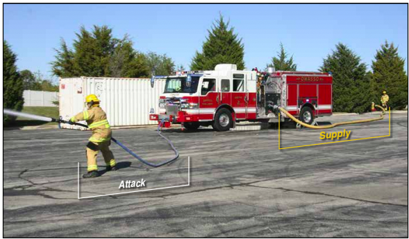
Attack hose transports water or other agents, at increased pressure, from the following sources (Figure 12.1):
- From the pump-equipped apparatus to a nozzle or nozzles
- From a pump-equipped apparatus to a fire department connection (FDC) mounted on a structure
- From a building standpipe to the point the water is applied to the fire
Hose Sizes
Fire hose is manufactured in sizes and lengths based on specifications in NFPA 1961, Standard on Fire Hose. Hose size is described in terms of hose diameter and length.
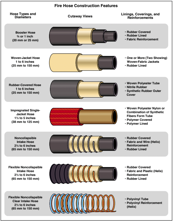
Hose Diameter
The size of a fire hose refers to its inside diameter. According to NFPA, the hose’s internal diameter should not be less than its advertised or labelled hose size. For example, hose labeled 3 inches (77 mm) in diameter must have an internal diameter of 3 inches (77 mm) (Figure 12.2). Some types of fire hose can expand beyond the manufactured internal diameter because of the elastic qualities of modern materials used in its construction. Expansion increases the interior diameter when the hoseline is pressurized with water and lowers friction loss. Not all fire hoses exhibit these characteristics. The performance of a hoseline depends on the materials and methods used in its construction.
Hose Length
Both attack and supply fire hose are manufactured in 50-or 100-foot (15 or 30 m) sections. While these lengths were traditionally determined for convenience and ease of handling, the traditional length of fire hose in North America is 50 feet (15 m) per section. Modern hose may be manufactured or carried in longer sections because it is often constructed of high-strength, lightweight synthetic materials that have the same relative weight of traditional sections of hose.
Suction hose (also called intake hose), used to connect the pumper to a hydrant or other water source, is manufactured in minimum lengths specified in NFPA 1901, Standard for Automotive Fire Apparatus. Large soft sleeve hose connects the pumper intake to a pressurized water source. Although historically referred to as soft suction hose, soft sleeve hose is not rigid and cannot be used for drafting because it will collapse. Soft sleeve hose is available in sizes ranging from 21⁄2 to 6 inches (65 to 150 mm).
Hard suction hose is generally constructed in 10-foot (3 m) long sections and is designed for drafting water from static water supplies or connecting to a fire hydrant. Some hard-suction hose is constructed of a rubberized, reinforced material; others are made of heavy-duty corrugated plastic. Hard-suction hose is available in sizes ranging from 21⁄2 to 6 inches (65 to 150 mm).
Hose Couplings
Fire hose couplings connect hose sections to form a continuous hoseline and to connect fire hoses to nozzles, hydrants, pumper connections, and FDCs. To ensure compatibility with all brands of fire hose, NFPA 1963, Standard for Fire Hose Connections specifies fire hose coupling design and construction. The dimensions required of American National Fire Hose Connection Screw Threads, commonly called National Hose (NH) (Figure 12.3). Using fire hose with national standard threads means that two or more fire departments that respond together can connect their fire hose sections.


** NOTE:Some jurisdictions do not use National Standard threads. When connecting to hydrants or apparatus in those jurisdictions as part of mutual aid, hose adapters may be needed to complete the connection. **
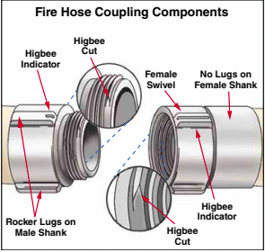
Both attack hose and supply hose may be equipped with either threaded or non-threaded couplings (Figure 12.4). Coupling and uncoupling are simple procedures for connecting and disconnecting sections of hose with either of these types of couplings. The need for speed and efficiency under emergency conditions requires firefighters to practice techniques for coupling and uncoupling until they are able to perform these actions quickly and efficiently. Nozzles are connected or removed from the fire hose using the same methods as those used for coupling and uncoupling sections of hose.
Skill Sheet 12-1 describes methods of coupling and uncoupling threaded and nonthreaded fire hose. The sections that follow describe the characteristics of threaded and non-threaded couplings.
Threaded Couplings
One of the oldest coupling designs involves the casting or machining of a spiral thread into the face of two distinctly different couplings — male and female. A male coupling thread is cut on the exterior surface, while a female coupling thread is on the interior surface of a free-turning ring called a swivel. The swivel permits connecting two sections of hose without twisting the entire hose. Each section of fire hose with threaded couplings has a male coupling at one end and a female coupling at the other.
Unlike common pipe threads that are relatively fine, fire hose coupling threads are coarse (with wide tolerances) which allows the couplings to be connected quickly. Some manufacturers make the large coupling sizes (31⁄2 inches [90 mm] and above) with ball bearings or roller bearings under the swivel to ensure their smooth operation. A removable rubber gasket located inside the base of the female coupling ensures a tight fit and reduces water leaks.
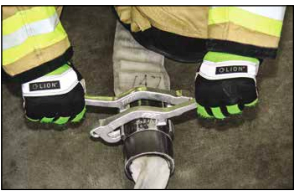
Threaded couplings are manufactured with either lugs or handles to aid in tightening and loosening connections. Lugs sit on the shank of a male coupling and on the swivel of a female coupling. Lugs are grasping points where firefighters can easily hold the coupling when making and breaking coupling connections. Connections may be made manually or with spanner wrenches (special wrenches that fit against the lugs, also called spanners) (Figure 12.6). Three types of lugs are found: pin, recessed, and rocker (Figure 12.7).
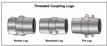
Pin lugs, usually found on old fire hose couplings, resemble small pegs. Although still available, pin lug couplings are infrequently ordered with new fire hose because they tend to catch when hose is dragged over objects or deployed from the hose bed of a pumping apparatus (Figure 12.8). Booster fire hose has couplings with recessed lugs, shallow holes drilled into the coupling. This lug design pre-vents abrasion that would occur if the hose had protruding lugs and was wound onto reels. Firefighters need a pin lug spanner wrench inserted into the recessed lug holes to tighten or loosen the couplings.
Modern threaded couplings have rounded rocker lugs. The rounded shape of rocker lugs (unlike pin lugs) helps prevent the hose from catching on objects. On the couplings, one of the rocker lugs on the swivel is scalloped with a shallow indentation (the Higbee indicator) to mark where the Higbee cut begins.
Handles or extended lugs are located on the swivels of large intake supply or suction hoses. Firefighters can grasp these handles when tightening the large coupling that connects the hose to a pump valve intake. If necessary, striking the handles with a rubber mallet can help loosen the coupling or tighten leaking couplings on a charged line. You may need to use the mallet for tightening during the setup for a drafting operation, for example.
Non-threaded Couplings
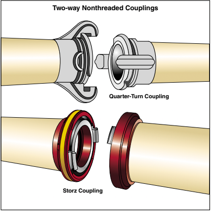
Nonthreaded couplings connect using locks or cams rather than screw threads. Although some non-threaded couplings have male and female ends, two-way couplings are more prevalent in North America. A two-way coupling set has identical couplings rather than distinct male and female couplings.
Two-way couplings come in two varieties:
- Quarter-turn
- Storz (Figure 12.9).
The quarter-turn coupling has two hook-like lugs on each coupling. The lugs, which are grooved on the underside, extend past a raised lip or ring on the open end of the coupling. When the couplings are mated, the lug of one coupling slips over the ring of the opposite coupling and then rotates 90 degrees clockwise to lock. A gasket on the face of each coupling seals the connection to prevent leakage.
Storz couplings are most found on large diameter hose. Like quarter-turn couplings, they are joined and then rotated until locked in place to form a connection. Unlike quarter-turn couplings, the locking components consist of grooved lugs and inset rings built into the face of each coupling swivel. When mated, the lugs of each coupling fit into recesses in the opposing coupling ring and slide into locking position behind the ring with a one-third-turn rotation. External lugs at the rear of the swivel provide leverage for connecting and disconnecting couplings. On most manufacturers’ couplings, the lugs align to give a visual indicator of a connected coupling (couplings properly aligned and locked in place).
Nonthreaded couplings have the following advantages:
- Fire hose can be connected quickly. However, the use of spanner wrenches to ensure a complete connection slows the connecting operation slightly.
- There is no risk of cross-threading a connection and damaging a coupling because there are no threads.
- Double-male or double-female adapters (adapters connecting two threaded couplings of the same thread type, size, and sex) are not needed, thus hose can be deployed from the hose bed regardless of hose load type.
Non-threaded couplings also have disadvantages:
- Hose can become uncoupled, often suddenly and violently, if a complete connection has not been made.
- Hydrants require an adapter to make connections with non-threaded couplings.
- The time needed to attach the adapter increases the time required to connect to the hydrant and begin deploying hose.
- Dirt and other large debris can become lodged inside the coupling’s grooves, giving the impression that a tight seal has been made when the hose is actually not connected.
** NOTE: Some fire and emergency service organizations that have adopted two-way couplings for their supply hose operations use permanent adapters installed on hydrants for fire hydrant connections. **
Inspection, Care, and Maintenance of Fire Hose
Thorough inspection, care, and maintenance can significantly extend the working life of fire hose. The techniques for washing and drying and the provisions for storage are very important functions in the care of fire hose.
Inspecting Hose
According to NFPA 1962, hose should be inspected and service-tested within 90 days before being placed in service for the first time and at least annually thereafter. Each time a section of hose gets used, whether for emergency incidents or training, it should be inspected to ensure that it is free of visible soil or damage. Check couplings for ease of operation, deformations, or other damage. While gathering equipment and rolling fire hose immediately following an incident, conduct a brief inspection. This inspection allows firefighters to identify and mark damage on hose and couplings immediately.
Refer to Skill Sheet 12-2 for general procedures for inspecting and maintaining fire hose.
Before fire hose and couplings are stored or placed back in service after use, correct or report any of the fol-lowing deficiencies:
- Evidence of dirt or debris on the hose jacket or couplings
- Damage to the hose jacket
- Coupling loosened from the hose
- Damage to male and female threads
- Obstructed operation of the swivel
- Absence of a well-fitting gasket in the swivel
Washing Hose
The method used to wash fire hose depends on the type of hose. Hard rubber booster hose, hard intake hose, and rubber-jacket collapsible hose only require rinsing with clear water, although a mild soap may be used if necessary.
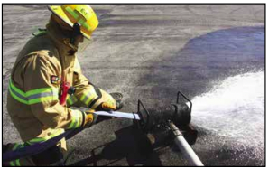
Most woven-jacket fire hose requires a little more care. After the woven-jacket hose is used, any dust and dirt should be thoroughly brushed or swept off of the hose. If brushing or sweeping does not remove the dirt, wash it with clear water while scrubbing with a stiff brush (Figure 12.10).
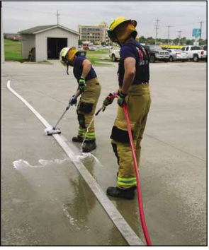
When fire hose has been exposed to oil, it should be washed with a mild soap or detergent using scrub brushes or straw brooms. Make sure that the oil is completely removed. The hose should then be rinsed thoroughly with clean water.
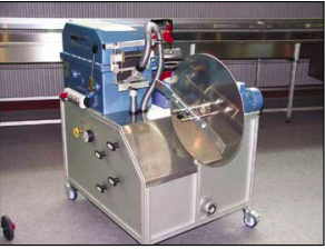
A hose washing machine can make the care and maintenance of fire hose much easier (Figure 12.11). The flow of water into this device can be adjusted as desired, and the movement of the water assists in propelling the hose through the device. The hoseline that supplies the washer with water can be connected to a pumper or used directly from a hydrant. Higher water pressures provide better results.
Many stations may have cabinet-type machines that wash,rinse, and drain fire hose. One person can operate this machine. It is self-propelled and can be used with or without detergents (Figure 12.12).
Drying Hose
Fire hose should be dried before being stored. The methods used to dry hose depend on the type of hose. It should be dried following departmental SOPs and the manufacturer’s recommendations. Woven-jacket, natural fibre hose must be thoroughly dried before being reloaded on an apparatus to prevent mildew. Water should be drained from hose to protect the lining. Hard rubber booster hose, hard intake hose, and synthetic jacket collapsible hose may be placed back on the apparatus while wet with no ill effects.
Hose towers and drying racks must have adequate ventilation and protection so that fire hose is not exposed to high temperatures or direct sunlight (Figure 12.13).
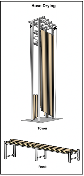
Take the following actions when drying hose in hose towers or on racks:
- Remove hose from exterior hose towers as soon as it is dry to protect it from sun damage.
- Lash or tie the coupling ends of hose hung on outside drying towers together to prevent them from swinging in the wind. Swinging couplings can collide with each other or with tower supports, resulting in mechanical damage
- Cover male threads with precut sections of tubing to provide additional protection.
- Incline drying racks enough to allow water to drain from the hose during drying.
- Avoid placing hose sections too close together or allowing them to touch, which can slow the drying process.
Storing Hose
After fire hose has been washed and dried, roll and store it in racks in a manner that protects it from damage. Mount racks permanently on the wall or stand them on the floor. Mobile hose racks can be used to store and move hose from storage rooms to apparatus for loading (Figure 12.14). If hose must be stored in the fire apparatus room/bay, inspect and clean it more frequently than fire hose that is stored in a separate space. Hose that is stored in the fire apparatus room/bay may be exposed to:
- Cleaning solvents
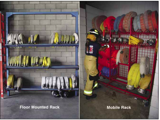
Figure 12. 14 - Lubricants
- Oil
- Gasoline
- Diesel fumes
- Other airborne contaminants
![]()
Take the following precautions to prevent damage to hose stored in racks:
- Locate hose racks in a clean, well-ventilated room that is easily accessible to the apparatus room/bay.
- Store hose where it is not exposed to direct sunlight. The sun’s ultraviolet rays break down the natural or synthetic fabric of the hose, reducing its expected service life.
- Pack cotton fabric hose loosely so that air circulates around it. Synthetic and rubber-jacketed hose can be stored in tight rolls after normal cleaning procedures.
- Store hose in a rack in such a way that couplings are not in walkways and will not come into contact with equipment or passing personnel.
- Roll the hose with the male end inside the roll to protect the male coupling threads.
- When it is necessary to store fire hose with the male coupling on the outside of the roll, protect the exposed threads with a cap or other protective device.
- Place two-way couplings in a storage rack in a way that prevents dirt or other foreign objects from collecting in their ramp grooves. These contaminants can interfere with their ability to securely lock into place.
Preventing Damage to Hose
The types of damage that can occur to the exterior covering and the inner lining of fire hose include:
- Mechanical damage: Abrasions, cuts, and tears
- Thermal damage: Exposure to fire, high heat, or freezing temperatures
- Organic damage: Mold and mildew
- Chemical damage: Deterioration due to solvent action on synthetic materials and natural fibres
- Corrosion: Rusting of metal couplings
- Age deterioration: Cracking at points where hose is folded and separation of inner liner from exterior covering
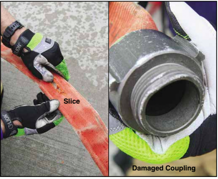
Mechanical Damage
Mechanical damage occurs when contact with an object or surface causes:
- Slices or cuts
- Rips or tears
- Abrasions on the exterior covering
- Crushed or damaged couplings
- Cracked inner linings
To prevent mechanical damage to fire hose, follow these recommended practices:
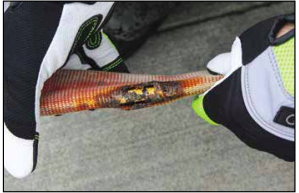
- Avoid laying or pulling a hose over rough, sharp edges or objects such as corners, cornices, parapets, and windowsills.
- Use a hose roller or place a folded salvage cover over sharp edges.
- Clear windowsills of broken glass fragments.
- Provide traffic control measures to prevent vehicles from driving over hose.
- Use hose ramps or bridges to protect hose from vehicles driving over it when traffic cannot be rerouted.
- Open and close nozzles, valves, and hydrants slowly to limit excessive stress and prevent water hammer.
- Provide chafing blocks to prevent abrasion to the hose when it vibrates near the pumper.
- Avoid excessive pump pressure on hoselines.
- Deploy hoselines away from debris, or clear debris from the path of hose during overhaul operations.
- Change the position of folds in the hose when reloading it on the apparatus.
- Clean the hose before reloading it to prevent abrasions from dirt or grit.
Thermal Damage
Thermal damage to fire hose can result from exposure to excessive heat or cold. Excessive heat exposure or direct flame contact can cause:
- Charring
- Melting
- Weakening the outer jacket
- Dehydration of the rubber lining
Inner linings can become dehydrated when the hose is hung to dry in a drying tower longer than necessary or when it is dried in direct sunlight. Mechanical hose dryers eliminate this concern but extend the time required to dry large amounts of hose due to limited capacity. To prevent thermal damage, follow these practices:
- Protect hose from exposure to excessive heat or fire when possible.
- Remove hose from any heated area as soon as it is dry.
- Use moderate temperature settings for mechanical drying. Warm air is much better than hot air.
- Keep the outside of woven-jacket fire hose dry when not in use.
- Run water through hose that has not been used for some time to keep the liner soft.
- Avoid laying fire hose on hot pavement to dry.
- Roll dry hose in a straight roll for storage to keep the liner from drying out.
- Prevent hose from coming in contact with, or being placed close to, vehicle exhaust systems.
- Use hose bed covers on apparatus to shield the hose from the sun.
Cold Damage Prevention
Cold damage occurs when water on the inside and/or the outside of a fire hose freezes. Fire departments in regions with severely cold temperatures should use special cold-resistant hose designed for use at temperatures down to -65°F (-54°C). Regardless of the type of fire hose used in extreme cold, allow some water to flow through the nozzle to prevent water from freezing inside the hose during intermittent use at fires.
Guidelines to Prevent Hose Freezing:
- Maintain water flow in intake hose by circulating water from a hydrant through the fire pump, then discharging it through a drain-off hose that routes water away from the pumping apparatus.
- Immediately drain and roll hose that is no longer needed for firefighting operations.
- Tighten all hose connections to prevent couplings from leaking and freezing.
When fire hose becomes frozen to an ice-covered surface, there are three ways to remove it:
- Melt the ice with a steam generating device.
- Chop the hose loose with axes.
- Leave the hose until the weather warms enough to melt the ice.
Guidelines for Removing Frozen Hose:
- Make all cuts well away from the hose when chopping it out of ice to minimize the chance of an axe blade striking and damaging the hose fabric.
- Avoid using exhaust manifold heat from the pumping apparatus; it can be very hot and poses a carbon monoxide hazard to firefighters.
- Wait until the hose is thawed before folding it. Folding frozen hose can damage the lining and outer jacket in ways that are not apparent during visual inspections.
- If fire hose sections can be uncoupled, carefully load them onto a flatbed vehicle and transport them to a location where they can be thawed and protected from damage.
- Perform a service test before placing thawed hose back in service to ensure that no damage has occurred.
Organic Damage
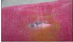
Mildew and mould are living organisms (fungi) that can rot natural fibres (Figure 12.17). When hose with a woven jacket of cotton or other natural fibre is stored wet, rot may weaken the jacket and can lead to ruptures under pressure. The outer jacket of some woven-jacket fire hose is made of synthetic fibers such as DacronTM polyester that resist organic damage. The outer jacket of some natural fibre hose has been chemically treated to resist mildew and mould, but such treatment is not always 100 percent effective. Rubber-jacket hose is not subject to organic damage.
Some methods to Preventing Mildew and Mould on Natural-Fibre, Woven-Jacket Hose:
- Remove all wet hose from the apparatus after use and replace it with dry hose or thoroughly dry the wet hose before reloading it on the apparatus.
- Inspect, wash, and dry hose that has been contaminated.
- Remove, inspect, sweep, and reload hose if it has not been unloaded from the apparatus during a period of six months. Ensure that the hose is folded at different points than when previously loaded.
- Inspect and test hose annually and after possible damage or freezing.
- Ensure that cotton or cotton blend fire hose is completely dry before storing or loading.
- Cover hose beds with water-repellant covers to keep hose loads dry during inclement weather.
- Periodically inspect fire hose in storage racks and hose beds.
- Remove and rotate hose periodically. Even if mildew is not visible, a musty smell may indicate its presence within the hose.
- Ventilate all areas where fire hose is kept, including pumping apparatus hose beds and compartments.
- Wash hose immediately whenever mildew is discovered using the following steps:
-
- Scrub the cover jacket with a very mild soap or manufacturer-recommended cleaning solution.
- Rinse well.
- Dry completely or to the point recommended in the manufacturer’s instructions.
- Inspect the hose section within the next few days for the reappearance of mildew.
Chemical Damage
Certain chemicals and chemical vapours can damage the outer jacket on fire hose or cause the rubber lining to separate from the inner jacket. Common examples of chemical damage include:
- Exposure to petroleum products, paints, acids, or alkalis, may weaken hose to the point of bursting under pressure.
- Battery acid can destroy hose jacket fibres.
- Runoff water from a fire may carry foreign materials that can cause chemical damage to fire hose. After exposure to chemicals or chemical vapours, hose should be cleaned as soon as is practical. Some recommended practices include:
- Avoid laying fire hose directly against curbs where oil, gasoline, and battery acid may accumulate or pool from parked automobiles.
- Place the hose 2 to 4 feet (0.6 to 1.2 m) away from the curb or gutter but not in vehicle travel lanes.
- Move the hose onto a sidewalk or into a median to avoid vehicle and contamination damage, if possible.
- Avoid exposing fire hose to hazardous materials spills.
- Avoid exposing fire hose to spills of foam concentrate, which is mildly corrosive and can deteriorate the hose lining or cover material if it remains on the hose.
- Thoroughly scrub fire hose suspected of having contacted acid or other caustic chemicals with a solution of bicarbonate of soda and water. Remove the hose from service and contact the manufacturer for additional maintenance procedures.
- Periodically remove hose from the apparatus, wash it with plain water, and dry it thoroughly.
- Test hose properly if there is any suspicion of damage.
- Dispose of hose according to departmental SOPs if it has been exposed to hazardous materials and cannot be decontaminated.
Corrosion
Corrosion happens when a substance in the environment gradually weakens metal over time. The metal is slowly converted into a weaker compound. The most common fire hose coupling metals are brass and aluminum. Each of these metals possesses a high resistance to corrosion but each will suffer some deterioration when exposed to certain conditions.
Brass is highly resistant to corrosion. Over time, however, a brass coupling will corrode when it is in con-tact with moist organic materials or earth. The metal will darken and turn green as copper oxides are formed. Although these copper oxides are usually found only on exposed surfaces, they can form on the interior of female swivels or inside surfaces of nozzles, reducing the ease of the device’s operation. Normal cleaning removes most of the surface corrosion; however, the only way to free the swivels or operating mechanisms is to lubricate moving parts according to the manufacturer’s recommendations.
Aluminum couplings develop a layer of corrosion (aluminum oxide) that in effect “seals” the metal against further oxidation. This protective layer can be scratched or abraded during normal use, resulting in the formation of a new layer.
Age Deterioration
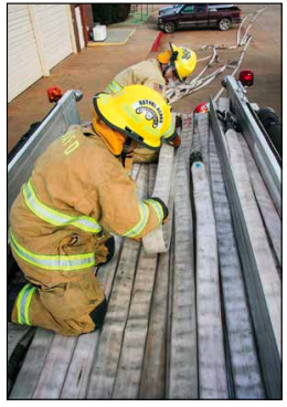
If fire hose is left in an apparatus bed for a long time, it can deteriorate and crack because of the sharp folds in the tightly-packed hose load. To prevent this, unused hose loads should be removed and repacked on a regular schedule. Because the hose near the top of the hose bed is deployed most often, lower layers may seldom be removed. When reloading the hose, pack the hose loosely and fold the hose in places where it was not previously folded (Figure 12.18). Because fire hose that is loaded on edge wears more quickly, manufacturers recommend using a flat load.
Fire hose will deteriorate if it is left hanging in a hose tower for excessive periods. The inner lining of hose can become weakened at the point where it hangs over the support peg. Reinforced jacketed fabric hose may suffer a separation of the rubber or plastic lining from the inner reinforcement, reducing the strength of the hose at the point of the separation. To prevent this damage, remove the hose from the tower as soon as it is dry. If fire hose must remain in a tower for prolonged periods, change the hose/peg contact point periodically.
** NOTE: Always follow the manufacturer’s instructions and department SOPs for hose care and maintenance. **
Lesson 3
Outcomes:
- Explain methods of rolling hose.
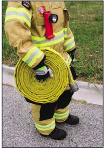
Hose Rolls
There are several methods for rolling fire hose, depending on whether it’s intended for use or storage. Care must always be taken to protect the couplings.
Common hose rolls include:
- Straight Roll
- Donut Roll
- Twin Donut Roll
Straight Roll
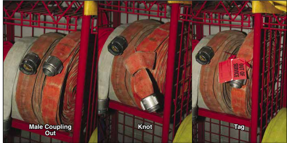
Variations of the straight roll indicate if a section of hose needs repair or testing before use. For example, starting the roll at the female coupling exposes the male coupling, or tying a knot or attaching a tag to indicate damage.
The straight roll is used for:
- Transporting damaged or dirty hose for repair, replacement, or cleaning.
- Storing sections of hose.
- Carrying spare sections of hose in apparatus compartments.
- Making hose loading easier.
Donut Roll
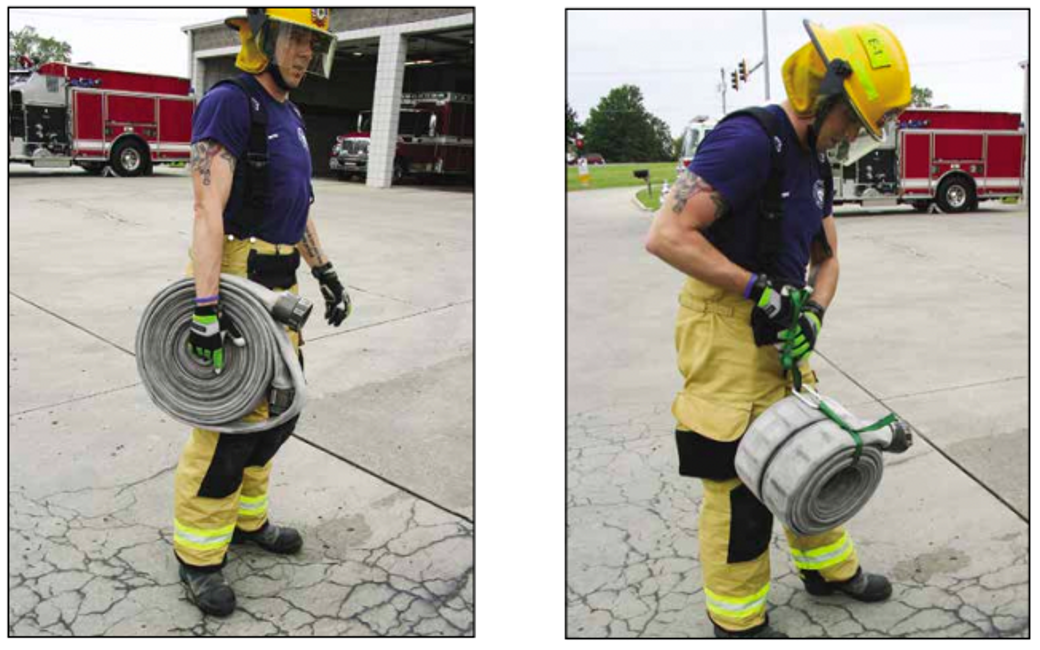
The Donut roll offers several advantages over the straight roll:
- Provides control of both couplings, protecting them from damage.
- Hose rolls out easier with fewer twists or kinks.
- Enables quicker connection to other couplings.
Twin Donut Roll
The following demonstrates its operation:
- Skill Sheet 12-4 describes a method for making the twin donut roll.
- If the couplings are offset by about 1 foot (0.3 m) at the beginning, they can be coupled together after the roll is tied or strapped.
- A hose strap inserted into the centre of the roll is used to carry the hose roll, making it convenient for transportation and carrying during operations.
Hose Loads
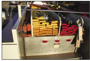
NFPA 1901, Standard for Automotive Fire Apparatus, lists the minimum quantity of hose in various sizes to be carried on a standard pumping apparatus. There must be a minimum 800 feet (240 m) of 21⁄2-inch (65 mm) or larger fire supply hose and 400 feet (120 m) of 11⁄2-inch (38 mm), 13⁄4-inch (45 mm), or 2-inch (52 mm) attack fire hose. Supply and attack hose is generally carried in open compartments called hose beds. Hose beds vary in location, size, and shape, and are sometimes built for specific needs. The front of the hose bed is that part of the compartment closest to the front of the apparatus, and the rear of the hose bed is that part of the compartment closest to the rear of the apparatus. Most hose beds have open aluminum slats in the bottom that allow air to circulate throughout the hose load to prevent mildew damage to woven-jacketed hose.
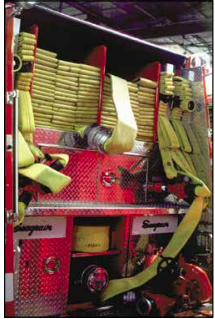
Apparatus hose beds may be a single compartment, or a vertical panel that runs from the front to the rear of the hose bed may create separate compartments. This division creates a split hose bed allowing the apparatus to have hose loaded that can be deployed as a single or double supply line or for both forward and reverse hose lays at the same time. Hose in a split bed should be stored so that both beds may be connected when a long hose lay is required (Figure 12.23).
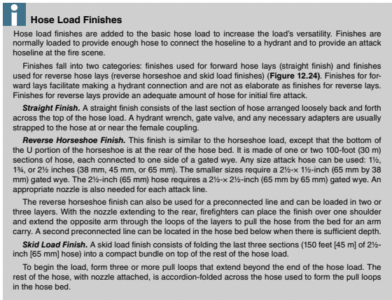
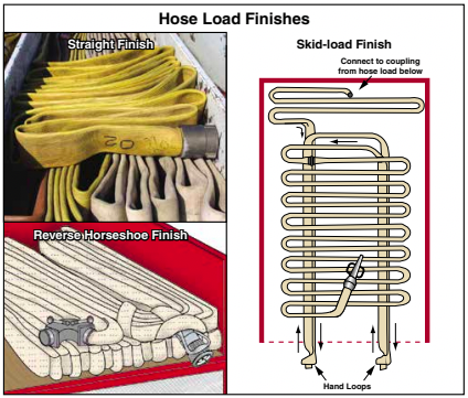
The three most common loads for supply hoselines are the flat, accordion, and horseshoe. Hose loads may also have a finish: an additional section connected to the hose load and arranged on the top of the load, which can be rapidly deployed for forward or reverse supply hose lays or as an attack line.
** NOTE: Additional supply and attack hose may be carried in compartments on the apparatus. **
Hose Loading Guidelines
Although loading hose on fire apparatus is not an emergency operation, it must be done correctly so that hose is easily accessible at a scene. During an emergency, properly loaded hose can be efficiently and effectively deployed for supply or attack operations.
The following general guidelines should be followed:
- Check gaskets and swivel before connecting any coupling.
- Keep the flat sides of the hose in the same plane when two sections of hose are connected. Lugs on the couplings do not need to be aligned.
- Tighten the couplings hand tight.
- Remove kinks and twists from fire hose when it is bent to form a loop in the hose bed.
- Make a short fold or reverse bend, called a Dutchman, in the hose during the loading process so that couplings are not too close to the front or rear of the hose bed and will not flip when pulled out of the bed. The Dutchman serves two purposes: it changes the direction and/or location of a coupling (Figure 12.25).
- The reverse bends should not be overused in the same layer because it can wedge couplings in the bed.
- Load large diameter hose (31⁄2-inch [90 mm] or larger) with all couplings near the front of the bed. This saves space and allows the hose to lie flat (Figure 12.26).
- Do not pack hose too tightly; it puts excess pressure on the folds of the hose and may cause couplings to snag when the hose pays out of the bed. Hose should be loose enough to allow a gloved hand to be easily inserted between folds (Figure 12.27).

Loading large diameter hose can be time-consuming work. To make the effort more efficient, many apparatus equipped with LDH carry LDH rollers. The roller is a wider version of a hose roller. It mounts temporarily on the tailboard of the pumper. With the hoseline laid between the wheels along the length of the apparatus, the apparatus is slowly driven along the hoseline. As the apparatus moves, the hose is pulled over the roller and into the hose bed. Because the hose may need to be guided over the roller, this is one of the very few times firefighters can stand on the tailboard or ride in the hose bed while the apparatus is in motion. Firefighters riding on the apparatus while loading hose should be safety harnessed to the apparatus.
Flat Load
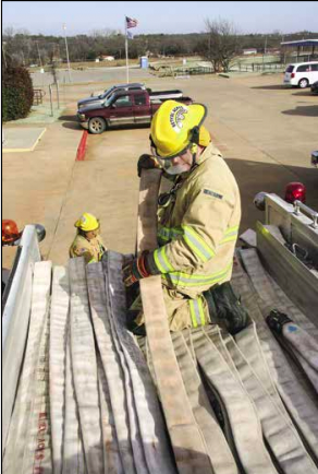
Of the three supply hose loads, the flat load is the easiest to load. It works for any size of supply hose and is the best way to load large-diameter hose. As the name implies, the hose is laid so that its folds lie flat rather than on edge (Figure 12.28). Hose loaded in this manner is less likely to damage from apparatus vibration during travel. A disadvantage of this load is that the hose folds contain sharp bends at both ends of the bed, which requires that the hose be reloaded periodically to change the location of the bends within each length to prevent damage to the lining.
In a single hose bed, the flat load may be started on either side. In a split hose bed, lay the first length against the partition with the coupling hanging far enough below the hose bed so that the coupling can be connected to the last coupling of the load on the opposite side and laid on top of the load. This placement allows the couplings to be easily disconnected when the load must be divided to lay dual lines. How far the coupling needs to hang is based on an estimate of the anticipated height of the hose bed.
Skill Sheet 12-5 demonstrates the proper method for making a flat load.
The hose load for large diameter hose should be started 12 to 18 inches (300 to 450 mm) from the front of the hose bed. This extra space should be reserved for couplings, and all couplings should be laid to allow them to deploy without flipping over. It may be necessary to make a short fold or reverse bend in the hose to do this.
Accordion Load
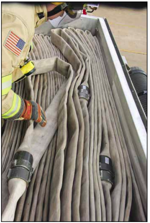
The accordion load is named for how the hose appears after loading. The hose is laid on edge in folds that lie adjacent to each other (Figure 12.29). The first coupling is placed in the rear of the bed. In a single hose bed, it can be placed in either corner. An accordion load is easy to load, only requiring two or three people to load the hose, although four people are best. Another advantage is that firefighters can easily pick up a number of folds and place them on one shoulder to carry the hose from the bed. Skill Sheet 12-6 shows the procedures for making an accordion load.
Combination Load
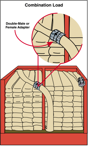
Combination loads are used in split hose beds that are loaded with threaded coupling hose. This load permits the apparatus to make a forward lay from the water source to the fire, followed by a reverse lay back to the water source. One half of the bed is loaded with the female coupling exposed and other half has the male coupling ex-posed. Where the two beds are connected, a double-female adapter fitting is used (Figure 12.30). This load can be a flat, accordion, or horseshoe load.
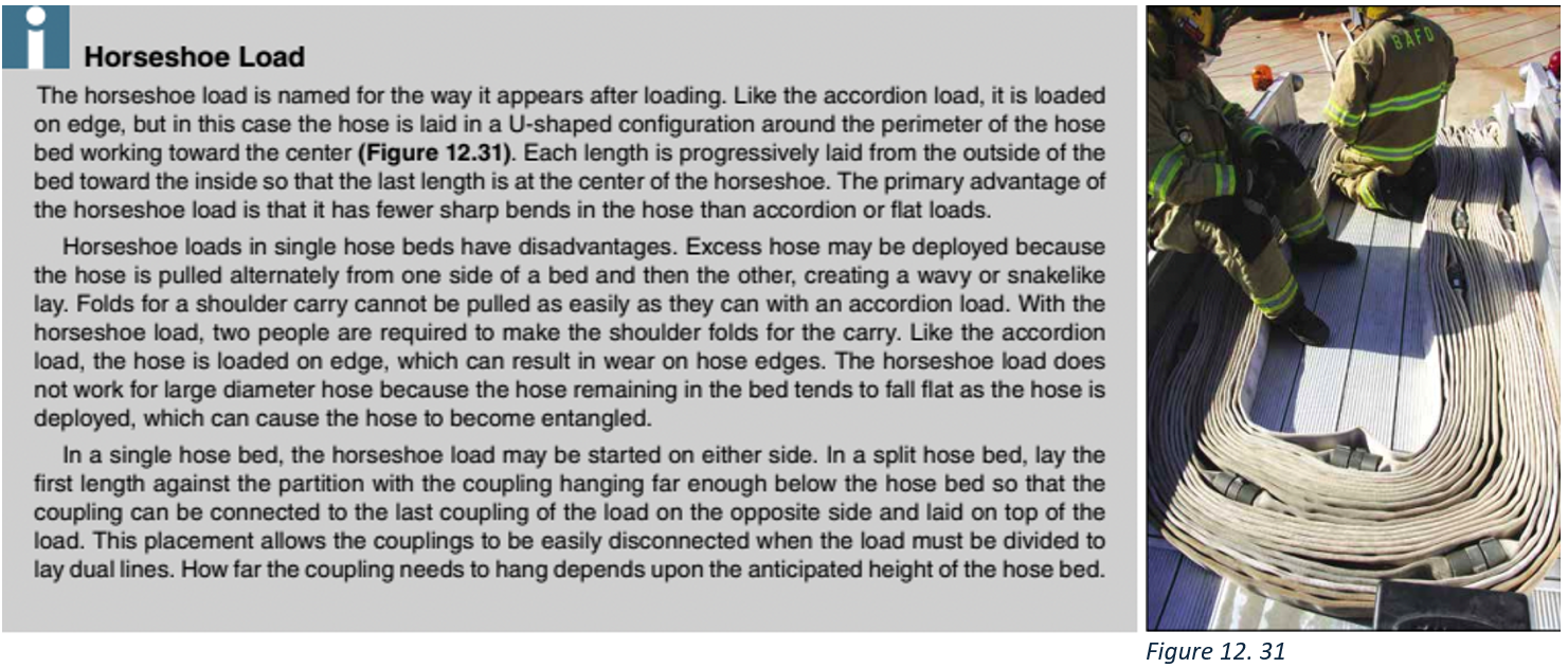
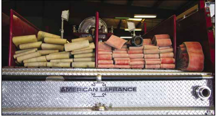
Another version of a combination load has large diameter supply hose loaded on one side of the bed and smaller-diameter hose that can be used for either supply or attack loaded on the other side (Figure 12.32). A pumper loaded in this manner can lay LDH when the fire situation requires the pumper to lay its own supply line and work alone, laying it forward so the pumper stays at the incident scene. Firefighters can use small-diameter hose as a supply line at fires with less demanding water flow requirements as well as for attack lines on large fires. Therefore, a split hose bed gives fire officers the greatest number of choices when determining the best way to use limited resources.
Pre-connected Hose Loads for Attack Lines
Pre-connected hoselines, called simply pre-connects, are the primary lines most fire departments use for fire attack. These hoselines are connected to a discharge valve and get placed in an area other than the main hose bed. Preconnected hoselines generally range from 50 to 250 feet (15 m to 75 m) in length. Preconnected attack lines can be carried in the following places (Figure 12.33):
- Longitudinal beds
- Raised trays
- Transverse beds (sometimes called cross lays or Mattydale hose beds)
- Tailboard compartments
- Side compartments or bins
- Front bumper wells (sometimes called jump lines)

Reels
The following sections describe some common loads for pre-connects. Special loads to meet local requirements may be developed based on individual experiences and apparatus configurations. Regardless of the type of load used, the preconnected attack hose must be fully deployed from the hose bed before charging the line. In some departments, this is referred to as “clearing the bed” and is the responsibility of the driver/operator or firefighter pulling the hose.
Preconnected Flat Load
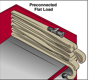
The preconnected flat load is adaptable for varying sizes of hose beds and is often used in transverse beds (Figure 12.34). This load is similar to a flat load for larger supply hose except that exposed loops are provided for pulling the load from the bed. Place the loops at regular intervals within the load so that equal portions of the load are pulled from the bed. The number of loops and the intervals at which they are placed depend on the size and length of the hose.
Procedures for creating the pre-connected flat load are described in Skill Sheet 12-7.
Triple Layer Load
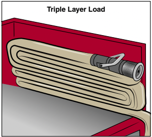
The triple layer load gets its name because the load begins with hose folded in three layers. The three folds are then laid into the bed in an S-shaped fashion (Figure 12.35). The load is designed for one person to pull.
The layers in a triple layer load may be as long as 50 feet (15 m) each. All of this hose must be removed from the bed before deploying the nozzle end of the hose which can be difficult or impossible if the space directly behind the hose bed is restricted. While this hose load can be used for all sizes of attack lines, it is often preferred for larger (2-and 21⁄2-inch [50 and 65 mm]) attack lines that may be too cumbersome for shoulder carries.
The procedures for making the triple layer load are given in Skill Sheet 12-8.
Minuteman Load
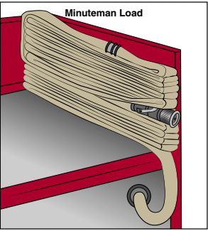
One person can pull and advance the minuteman load. This load can be carried on the shoulder completely clear of the ground, which makes it less likely that the hose will catch on obstacles. The load deploys from the shoulder as the firefighter advances toward the fire. The load is also particularly well-suited for a narrow hose bed (Figure 12.36). However, it can be awkward to carry when wearing an SCBA. If the load is in a single stack, it may also collapse on the shoulder if not held tightly in place.
The procedures for making the minuteman load are described in Skill Sheet 12-9.
Booster Hose Reels
Booster hoselines are rubber-covered hose that are usually carried pre-connected and coiled on reels (Figure 12.37). The hose’s diameter and length may vary. The hose works well for a quick, first attack on small exterior fires. Direct connection provides instant water flow no matter what length of hose is needed.
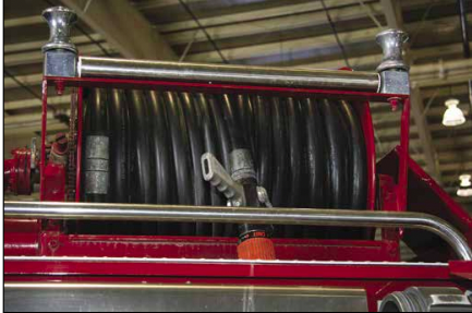
These booster hose reels may be mounted in several places on the apparatus according to specified needs and apparatus design. Some booster hose reels are mounted above the pump panel and behind the apparatus cab. This arrangement provides booster hose that can be unrolled from either side of the apparatus. Other booster hose reels mount on the front bumper of the apparatus or in rear compartments. Manual-and power-operated reels are available. In order to load the maximum amount of hose with the easiest removal from the reel, booster hose should be evenly wound onto the reel one layer at a time.

