58 Refrigeration
Learning Objectives
- Explain fundamentals of refrigeration
- Describe the identification, classification, and physical properties of refrigerants
- Describe the basic layout of compression refrigeration systems
- Describe the construction and operation of refrigeration compressors
- Describe the design of refrigeration evaporators and condensers
- Condenser operation and maintenance
- Troubleshoot cooling tower operation
- List the functional components of air conditioning systems
- Describe the operation of air conditioning systems
Essential Question
How is air cooled?
Introduction
Definition: “the thermodynamic process of lowering the temperature of a substance below the temperature of its surroundings and maintaining this substance at the lower temperature” (PanGlobal, 2017, 15-3)
This process is the process of transferring heat from the entity into an entity with a cooler temperature (this is called a refrigerant). When there is a loss of heat, it makes the temperature get lower and the entity to become cooler. Sensible heat is the heat that is lost from the first entity. This heat is absorbed by the refrigerant, BUT it does not increase the temperature. It will actually change the state of the refrigerant. This absorbed heat is called latent heat.
Example
An example of this principle is an icebox:
| Refrigerant | In an icebox, the refrigerant is the ice. As the ice melts, it absorbs heat from the air and the items stored in the icebox, cooling them down. |
| Latent Heat | When the ice absorbs heat and melts, it undergoes a phase change from solid to liquid, absorbing latent heat in the process. This latent heat absorption keeps the icebox interior cool. |
| Sensible Heat | The air inside the icebox and the items stored in it transfer sensible heat to the ice as they come into contact with it. This sensible heat transfer lowers the temperature of the air and the items, contributing to the cooling effect. |
| Heat Transfer Medium | The air inside the icebox acts as the heat transfer medium. It circulates around the items stored in the icebox, facilitating the exchange of heat with the ice. The air carries heat away from the items and transfers it to the ice, where it is absorbed. |
| Role of Air | The air inside the icebox plays a crucial role in transferring heat from the items to the ice. As the air circulates, it continuously exchanges heat with the items and the ice, helping to maintain a cool temperature inside the icebox. |
| Storage Compartment | The storage compartment of the icebox provides space to store items that need to be kept cold. The cooling effect generated by the melting ice ensures that the items remain chilled while stored in the compartment. |
In summary, the icebox example illustrates how the ice acts as a refrigerant, absorbing latent heat to melt and provide cooling. Sensible heat transfer occurs between the items stored in the icebox and the ice, facilitated by the circulating air. The air serves as the heat transfer medium, facilitating the exchange of heat between the items and the ice. The storage compartment provides a space to store items while benefiting from the cooling effect generated by the ice.
Disadvantages of Ice as a Refrigerant
- The lowest temperature obtainable is 0°C (32°F)
- Regularly add ice
- Need to discard the water
- Hard to control the temperature
Example
Another example of this principle is a felt-covered canteen used in dry, hot regions to keep drinking water cool.
- Refrigerant: In this example, the refrigerant is the water inside the canteen. As water evaporates from the surface of the felt, it absorbs heat from the surrounding environment, including the water inside the canteen. This absorption of heat causes the temperature of the water inside the canteen to decrease, providing the cooling effect.
- Latent Heat: When water evaporates from the surface of the felt, it undergoes a phase change from liquid to vapor. This process requires energy in the form of heat, known as latent heat. The latent heat absorbed from the surrounding environment during evaporation is what cools the water inside the canteen.
- Sensible Heat: As the water inside the canteen cools down, it transfers sensible heat to the felt and the air surrounding the canteen. This sensible heat transfer occurs as the water loses heat to its surroundings, further contributing to the cooling effect.
- Heat Transfer Medium (Air): The air surrounding the felt-covered canteen acts as the heat transfer medium. As water evaporates from the surface of the felt, it releases heat into the surrounding air. The air then carries this heat away from the canteen, helping to maintain a cool temperature inside.
In summary, the felt-covered canteen example demonstrates how water acts as the refrigerant, evaporating from the surface of the felt and absorbing latent heat from the surroundings to provide cooling. Sensible heat is transferred from the water to the felt and the surrounding air, contributing to the overall cooling effect. The air serves as the heat transfer medium, carrying heat away from the canteen and helping to maintain a cool temperature inside.
Evaporation
Refrigeration by evaporation can happen by using vaporizing liquids (refrigerants). They have a low boiling point at atmospheric pressure. The evaporator is the container in which the refrigerant is vaporized.
Example
An example of refrigeration by evaporation is the cooling of R-12 (dichlorodifluoromethane) which boils at -28.8°C (-22°F).
| Refrigerant | R-12, also known as dichlorodifluoromethane, serves as the refrigerant in this example. As a refrigerant, R-12 is circulated through a closed loop system within a refrigeration device, such as an air conditioner or refrigerator. It undergoes phase changes to absorb and release heat, providing cooling within the system. |
| Latent Heat | R-12 undergoes a phase change from liquid to vapor within the refrigeration system. This phase change requires energy in the form of heat, known as latent heat. When R-12 evaporates, it absorbs heat from its surroundings, causing the temperature within the system to decrease. This absorption of heat provides the cooling effect required for refrigeration. |
| Sensible | As R-12 vaporizes and absorbs heat, it cools the surrounding environment within the refrigeration system. The surrounding air or fluid transfers sensible heat to the R-12, causing its temperature to rise. This sensible heat transfer occurs as heat from the surroundings is transferred to the refrigerant, further facilitating the refrigeration process. |
| Heat Transfer Medium |
|
Types of Refrigerants
There are many types of refrigerants used in the industry. This section will discuss the identification, classification and properties of refrigerants.
The following tables in this section are taken from PanGlobal (2017) under the Fair Use Policy.
Common Refrigerants
| Refrigerant Number | Chemical Formula | Chemical Name | Trade Name |
| R-11 | CCl 3 F | Trichlorofluoromethane | R-11 |
| R-12 | CCl 2 F 2 | Dichlorodifluoromethane | R-12 |
| R-22 | CHClF 2 | Chlorodifluoromethane | R-22 |
| R-113 | CCl 2 FCClF 2 | Trichlorotrifluoroethane | R-113 |
| R-114 | CClF 2 CClF 2 | Dichlorotetrafluoroethane | R-114 |
| R-717 | NH 3 | Ammonia | Ammonia |
Classification
Classified in the Canadian Standards Association B52 Mechanical Refrigeration Code according to their toxic and flammable categorization.
| Toxicity | Flammability | Examples | |
| Group A1 | Non-toxic | Non-flammable | R-11 Trichlorofluoromethane
R-22 Chlorodifluoromethane |
| Group A2 | Low toxicity | Flammable | R-142b 1-chloro-1. 1-difluoroethane
R-152a 1,1-difluoroethane |
| Group A3 | Low toxicity | Highly flammable | R-600 Butane
R-290 Propane |
| Group B1 | Highly toxic | Non-flammable | R-764 Sulphur dioxide |
| Group B2 | Highly toxic | Flammable | R-717 Ammonia |
| Group B3 | Highly toxic | Highly flammable | Very rare, special application only |
Characteristics
An ideal refrigerant should have the following characteristics:
- low boiling point at atmospheric pressure
- high latent heat capacity, requiring a large amount of heat to convert from a liquid to a gas after the boiling point
- fairly low condensing pressure
- neutral scent
- non-corrosive
- non flammable
- non explosive
- cost effective
An example of a characteristics’ comparison of three refrigerants.
| R-12 | R-22 | Ammonia | |
| Chemical symbol | CCl 2 F 2 | CHClF 2 | NH 3 |
| Refrigerant no. | R-12 | R-22 | R-717 |
| Boiling point at atmospheric pressure | -28°C (-21.6°F) | -40°C (-41.4°F) | -33.3°C (-27.9°F) |
| Evaporating pressure at -15°C (5°F) | 182.6 kPa (26.5 psi) abs | 292.7 kPa (42.9 psi) abs | 236.2 kPa (34.3 psi) abs |
| Evaporating pressure (absolute) at -15°C (5°F) | 182.6 kPa (26.5 psi) | 292.7 kPa (42.4 psi) | 236.2 kPa (34.3 psi) |
| Condensing pressure at 30°C (86°F) (absolute) | 745 kPa (108 psi) | 1191.9 kPa (173 psi) | 1165.8 kPa (169 psi) |
| Net refrigerant effect | 116.4 kJ/kg | 162.9 kJ/kg | 1103.5 (kJ/kg) |
| Flammable | No | No | Slightly |
| Explosive when mixed with air | No | No | Yes |
| Toxic | No | No | Yes |
| Corrosive effect on metals when water is present | None | None | Attacks copper and copper alloys |
| Effect of contact with foods | None | None | Spoils taste, may cause toxicity |
| Effective on lubricating oil | Mixes with mineral oil | mixes with mineral oil to some extent | Does not mix |
| Odor | None | None | Strong and offensive |
| Applications | Household & commercial refrigerating and air conditioning | Commercial & industrial refrigeration and air conditioning | Industrial & commercial refrigeration |
Physical Properties
| Miscibility | Definition: the ability to dissolve into oil and vice versa
In refrigeration, miscibility refers to the ability of refrigerants and oils to mix together uniformly when they come into contact. This property is crucial because refrigeration systems often rely on the circulation of refrigerant-oil mixtures to lubricate moving parts, enhance heat transfer, and maintain system efficiency. It means the ability of a refrigerant to dissolve or blend evenly with the lubricating oil used in the refrigeration system. Ideally, refrigerants should be miscible with oil to form a stable solution that can effectively lubricate compressor components and facilitate heat transfer. A refrigerant that is miscible with oil will ensure proper lubrication and minimize wear and tear on system components. Conversely, miscibility in terms of oil dissolving in refrigerant refers to the ability of oil to dissolve or disperse within the refrigerant. While refrigerants are primarily gases or liquids, they can still absorb small amounts of oil, especially during compressor operation. However, excessive oil entrainment in the refrigerant can lead to poor heat transfer, reduced system efficiency, and potential damage to downstream components such as expansion valves and heat exchangers. Therefore, it is important to select refrigerants and oils that exhibit good miscibility to ensure optimal performance and longevity of refrigeration systems. |
| Leakage Tendency | Definition: leakage tendency refers to how likely a substance is to escape from a sealed system or container over time.
It indicates how prone a substance is to migrate through barriers or openings, leading to unintended loss or release into the surrounding environment. In refrigeration systems, for example, refrigerant leakage can occur due to factors such as operating pressure, viscosity, and density. The leakage tendency of a substance can be related to its molecular mass. Generally, substances with lower molecular masses may have higher leakage tendencies because their smaller molecules can more easily pass through barriers or openings in a sealed system. Conversely, substances with higher molecular masses may have lower leakage tendencies because their larger molecules are less likely to migrate through such barriers. However, other factors such as pressure, temperature, and chemical properties also play significant roles in determining the leakage tendency of a substance. Therefore, understanding the leakage tendency of substances is crucial for proper system maintenance, leak detection, and environmental management. |
| Odor | Refrigerants can have various odors, depending on their chemical composition. Some refrigerants have no odor, while others may have a characteristic smell that can range from faint to strong. However, it’s essential to note that many refrigerants are odorless or have odors that are not easily detectable at low concentrations. Odors can also be masked by additives or contaminants present in the refrigerant. In some cases, refrigerant leaks may produce noticeable odors, which can help in detecting leaks and addressing potential safety concerns. A substance with a really strong odor is not that advantageous because this can cause a public incident or commotion. Overall, the odor of refrigerants can vary widely, and it’s essential to follow proper safety protocols when handling them. |
| Toxicity | Refrigerants are categorized into groups according to their toxicity. Generally, they are not very toxic in low concentrations. However, when they come in contact with a flame or become very toxic. A halide torch can be used as a tool to detect leaks and repairs can be made using soldering or brazing, however ventilation must be available. |
| Flammability/Explosiveness | Among the refrigerants studied, ammonia is the only one that is combustible, and that too in concentrations between 16%-25% by volume in air. |
| Moise Reaction | Different refrigerants accumulate different amounts of moisture. When a refrigerant is at a high temperature, it can absorb more moisture, compared to when it is at a lower temperature. So, when a warm refrigerated saturated with moisture cools down, it will produce free water.
Moisture accumulation should be avoided:
|
Refrigeration Systems
Definition: A refrigeration system is a mechanical setup that transfers heat from one place to another, creating a cooling effect. It typically involves components like compressors, condensers, evaporators, and refrigerant lines, working together to achieve cooling.
Compression Refrigeration Systems
A compression refrigeration system is a type of refrigeration system that operates by compressing a refrigerant gas to increase its pressure and temperature. The compressed refrigerant is then condensed to a liquid state, releasing heat in the process. The high-pressure liquid refrigerant passes through an expansion valve, where it undergoes a rapid expansion, leading to a decrease in pressure and temperature. This low-pressure, low-temperature refrigerant then absorbs heat from the surroundings, cooling the desired area or substance. Finally, the refrigerant returns to the compressor to restart the cycle. Compression refrigeration systems are widely used in various applications, including air conditioning, refrigeration, and industrial processes.
There are five principal parts in a simple closed-cycle compression refrigeration system:
- evaporator
- compressor
- condenser
- liquid refrigerant control or regulating valve
- liquid receiver
Some other components can also be found such as drier, sight glass, etc.
Construction
Here’s an overview of the construction of such a system:
| Compressor | The system begins with the compressor, which is usually located outside the refrigerated space. The compressor is responsible for compressing the low-pressure refrigerant vapor into a high-pressure gas. It may be powered by electricity or other sources of mechanical energy. |
| Condenser | After compression, the high-pressure, high-temperature refrigerant gas flows into the condenser coil, which is often located outside the refrigerated space or in a separate unit. In the condenser, the refrigerant releases heat to the surrounding environment and condenses into a high-pressure liquid. |
| Expansion Valve | The high-pressure liquid refrigerant then passes through an expansion valve or capillary tube, where its pressure is rapidly reduced. This sudden drop in pressure causes the refrigerant to expand and partially vaporize, leading to a decrease in temperature. |
| Evaporator | The low-pressure, low-temperature refrigerant liquid-vapor mixture then enters the evaporator coil, which is typically located inside the refrigerated space. Here, the refrigerant absorbs heat from the surrounding environment, causing it to evaporate fully into a low-pressure vapor. This absorption of heat cools the refrigerated space. |
| Refrigerant Lines | The various components of the refrigeration system are connected by refrigerant lines, which transport the refrigerant between the compressor, condenser, expansion valve, and evaporator. |
| Control Systems | The refrigeration system may also include control systems, such as thermostats and pressure sensors, to regulate the operation of the compressor and other components based on temperature and pressure conditions. |
Overall, the construction of a compression refrigeration system involves assembling these components in a specific configuration to create a closed-loop cycle that efficiently removes heat from the refrigerated space, providing cooling as desired.
Operation
A compression refrigeration system is a type of refrigeration system that operates based on the compression and expansion of a refrigerant. Here’s a simplified overview of how it works:
| Compression | The process begins with the compressor, which compresses the low-pressure vaporized refrigerant into a high-pressure, high-temperature gas. This compression increases the energy and temperature of the refrigerant. |
| Condensation | The hot, high-pressure refrigerant gas then flows into the condenser coil, where it releases heat to the surrounding environment and condenses into a high-pressure liquid. This phase change from gas to liquid releases heat energy, causing the refrigerant to cool down. |
| Expansion | The high-pressure liquid refrigerant then passes through an expansion valve or capillary tube, where its pressure is rapidly reduced. This sudden drop in pressure causes the refrigerant to expand and partially vaporize, leading to a decrease in temperature. |
| Evaporation | The cold, low-pressure refrigerant liquid-vapor mixture then enters the evaporator coil, located inside the refrigerated space. Here, the refrigerant absorbs heat from the surrounding environment, causing it to evaporate fully into a low-pressure vapor. This absorption of heat cools the refrigerated space. |
| Return to the Compressor | The low-pressure vaporized refrigerant then returns to the compressor to restart the cycle. |
This continuous cycle of compression, condensation, expansion, and evaporation allows the compression refrigeration system to remove heat from a refrigerated space and maintain low temperatures. Compression refrigeration systems are widely used in various applications, including air conditioning, refrigeration, and industrial processes, due to their efficiency and effectiveness in cooling.
Refrigeration Compressors
Refrigeration compressors play a crucial role in compression refrigeration systems and are essential for various applications. The compressor’s role in a refrigeration system involves drawing in the vapor refrigerant from the evaporator, which is low in temperature and pressure, and subsequently increasing both its pressure and temperature. This can have the following results:
- Maintain low pressure in the evaporator so that the liquid refrigerant can boil off or evaporate at a boiling temperature that is below the temperature of the medium. So, the refrigerant can absorb the heat from the medium, which requires cooling.
- Maintaining high pressure of the refrigerant vapor entering the condenser so that the new saturation temperature is higher than the cooling medium, which results in the heat being rejected into the cooling medium.
There are three main classifications:
- Reciprocating Compressors: These compressors use a piston-cylinder arrangement to compress the refrigerant vapor. They operate with a reciprocating motion, where the piston moves back and forth within the cylinder to compress the refrigerant.
- Rotary Compressors: Rotary compressors utilize rotating mechanisms, such as vanes, scrolls, or screws, to compress the refrigerant vapor. They achieve compression through the rotational motion of these components, which traps and compresses the refrigerant as it moves through the compressor.
- Centrifugal Compressors: Centrifugal compressors employ centrifugal force to compress the refrigerant vapor. They utilize a rotating impeller to accelerate the refrigerant to high speeds, generating a centrifugal force that compresses the vapor against the compressor casing.
Construction
Overall, compressors in refrigeration systems are constructed with precision-engineered components that work together to compress refrigerant vapor and facilitate the refrigeration process. The specific design and construction vary depending on the type of compressor and its intended application.
| Reciprocating Compressors | Rotary Compressors | Centrifugal Compressors |
| Cylinder: Reciprocating compressors feature one or more cylinders where the compression process takes place. These cylinders contain a piston that moves up and down to compress the refrigerant vapor. | Compressor Body:
|
Impeller: Centrifugal compressors utilize a rotating impeller to accelerate the refrigerant vapor to high speeds. The impeller consists of blades or vanes that impart kinetic energy to the refrigerant. |
| Piston: The piston is a movable component within the cylinder that creates compression by reciprocating motion. It seals the refrigerant vapor within the cylinder during compression strokes. | Crankshaft:
|
Diffuser: After leaving the impeller, the high-speed refrigerant vapor enters a diffuser, where its velocity is converted into pressure. The diffuser slows down the refrigerant and redirects it towards the outlet. |
| Crankshaft: The crankshaft converts the rotary motion of the motor into reciprocating motion for the piston. It connects to the piston through a connecting rod. | Pistons and Connecting Rods:
|
Casing: The compressor casing surrounds the impeller and diffuser, providing structural support and maintaining proper alignment of components. |
| Valves: Reciprocating compressors have inlet and discharge valves that control the flow of refrigerant vapor into and out of the cylinder during compression cycles. | Suction and Discharge Valves:
|
Bearings: Bearings support the rotating shaft of the impeller and ensure smooth operation of the compressor. They reduce friction and allow the shaft to rotate freely. |
| Three types: open, hermetic (airtight), and serviceable or semi-hermetic | Safety Head:
|
|
Compressor Bearings:
|
Operation
| Reciprocating Compressors | Rotary Compressors | Centrifugal Compressors |
| Suction Stroke: The piston moves downward inside the cylinder, creating a vacuum that draws gas or air into the cylinder through an intake valve. | Intake Phase: Gas or air enters the compressor through an inlet port while the rotary mechanism is in motion. | Inlet Phase: Gas or air enters the compressor through an inlet port and flows into the center of a rotating impeller. |
| Discharge Stroke: The piston moves downward again, pushing any remaining gas or air out of the cylinder through the outlet valve. | Compression Phase: Inside the compressor, the gas or air gets trapped between the rotating element (such as screws, vanes, or lobes) and the compressor housing. As the rotating element spins, it reduces the volume of the gas or air, thus increasing its pressure. | Rotation: The impeller spins rapidly, imparting kinetic energy to the gas or air particles. As the gas or air moves radially outward from the center of the impeller, it gains speed and kinetic energy. |
| This cycle repeats continuously to maintain the desired pressure level. Reciprocating compressors are commonly used in various applications, including refrigeration, air conditioning, gas pipelines, and industrial processes, due to their ability to provide high pressure and relatively low flow rates. | Discharge Phase: Once the gas or air is compressed to the desired pressure, it is forced out of the compressor through a discharge port. | Compression: As the gas or air moves outward, it encounters a diffuser or volute casing surrounding the impeller. This casing converts the kinetic energy of the gas or air into pressure energy, causing the gas or air to slow down and increase in pressure. |
| Repeat: The process continues in a continuous cycle, with gas or air continuously entering the compressor, getting compressed, and then exiting at a higher pressure. | Discharge: The high-pressure gas or air exits the compressor through a discharge port located at the outer edge of the volute casing. | |
| Repeat: The process repeats continuously, with gas or air continuously entering the compressor, being accelerated and compressed by the impeller, and then exiting at a higher pressure. |
Evaporators
Definition: the part of the refrigeration system where the liquid refrigerant is vaporized by the absorption of heat from the medium to be cooled. There are two types of evaporators: dry/direct expansion evaporator and flooded evaporator.
| Dry/Direct Expansion Evaporator | Flooded Evaporator |
|
|
Construction Classification
- Bare Tube Evaporator:
- Consists of bare metal tubes arranged in a coil or bundle configuration.
- Tubes are typically made of materials like copper, aluminum, or stainless steel.
- Heat transfer occurs directly between the substance to be cooled and the outer surface of the tubes.
- Plate Surface Evaporator:
- Comprises a series of flat plates with fluid passages between them.
- Plates are usually made of materials like stainless steel or aluminum.
- Heat transfer occurs across the surface area of the plates as the refrigerant flows through the passages.
- Finned Tube Evaporator:
- Features metal tubes with extended surfaces, known as fins, attached along their length.
- Tubes are typically made of materials like copper or aluminum, while fins are often made of aluminum.
- Fins increase the surface area available for heat transfer, enhancing the evaporator’s efficiency.
- Shell and Tube Evaporator:
- Consists of a cylindrical shell containing multiple tubes arranged parallel to each other.
- Tubes are usually made of materials like copper, steel, or titanium, while the shell is typically made of steel.
- Refrigerant flows through the tubes, while the substance to be cooled circulates around the outside of the tubes.
- Heat transfer occurs through the tube walls, facilitating efficient cooling of the substance.
Condensers
Definition: the part of the refrigeration system where the superheated refrigerant vapor is cooled until it is condensed to a liquid and is subcooled. This process occurs after the refrigerant has absorbed heat from the substance or space being cooled in the evaporator and then compressed by the compressor.
There are generally three types of condensers: air-cooled, water-cooled, and evaporative.
| Air-Cooled Condenser | Water-Cooled Condenser | Evaporative Condenser |
|
|
|
Operation and Maintenance
A condenser may malfunction if the cooling water on the waterside surface is dirty or if there is an oil coating on the refrigerant side surface of the coils. It is important to properly use compressor lubricating oil and maintain proper refrigerant velocities to keep everything clean.
Non-condensable gasses
- Example: air
- This reduces its capacity which causes high compressor discharge pressures and temperatures.
- The refrigerant needs to be removed and be replace with new refrigerant.
Scale Formation
- If there are scale forming chemicals in the cooling water, it can be deposited on the waterside surfaces of the condenser.
- Scaling reduces the rate of heat transfer through the coil walls or tubes.
- This reduces the efficiency of the condenser and the refrigeration system in general.
- Tubes should be inspected regularly from the inside and outside so they can be cleaned immediately.
Oil Deposits
- The lubricating oils that are applied sometimes accumulate and create deposits on the refrigerant side of the coils and tubes.
- Oil will not breakdown if the system is being maintained and the temperature is not too high.
- Proper operation will ensure that it lasts a longer time.
Cleaning
- Take the unit out of service.
- Circulate an acid or chemical solution through the unit.
- Consult a qualified chemist or the manufacturer to ensure proper cleaning steps are being taken when working with chemicals.
- Shell and tube condensers that have straight tubes can be cleaned mechanically (or mechanical cleaners or brushed through the tubes).
Other Considerations
- Installing a water softening system (economical)
- Implement a regular maintenance schedule for condenser cleaning, inspection, and servicing. Follow manufacturer recommendations and industry best practices for maintenance tasks.
- Ensure proper airflow across the condenser coils in air-cooled condensers. Remove any obstructions or debris that may impede airflow and maintain adequate ventilation around the condenser unit.
Refrigeration Accessories
There are certain accessories that are used to aid or inspect the equipment. Each serves an important purpose. This section will cover some of the most common accessories that are used with refrigeration systems.
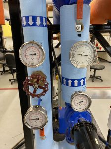
| Pressire Gauges
|
They show the pressure inside an evaporator and condenser, as well as the saturation temperatures. There are at least two pressure gauges in the refrigeration system. The first is connected to the high-pressure side and the second is connected to the low-temperature side. The gauges are also connected to the suction and discharge valves of the compressor. The pressure gauges should have pulsation dampeners, so the pointers don’t flicker due to the pulsations in pressure. Pressure gauges are not installed in low-capacity systems, such as residential appliances or window air conditioners or even in low-capacity commercial systems.
“The CSA Standard B52-09, Mechanical Refrigeration Code, Clause 5.8.3 that requires when a pressure gauge is permanently installed on the high side of a system, the gauge must be constructed for not less than 1.2 times the design pressure” (PanGlobal, 207, 20-3) |
| Oil Separators | The oil level in a compressor must be above its minimum level because there is always some oil that leaves the compressor with the high-pressure vapor, so there is a change too much oil leaves the compressor. So, it is important to separate the oil from the vapor and have it return to the compressor crankcase. IT is also important to avoid an accumulation of oil in the condenser because the oil coated on the tube surfaces will prevent proper heat transfer, which leads to high compressor discharge pressure and increased power consumption.
As the refrigerant vapor enters the separator casing, it undergoes a spinning motion. This spinning action, driven by centrifugal force, causes the oil droplets suspended in the vapor to accumulate along the walls of the vessel. Eventually, the collected oil drains downward to the bottom of the separator. |
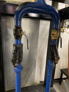
| Suction Strainers
|
Sometimes little bits of foreign matter can be brought into the compressor with the refrigerant vapor. This can cause damage to the compressor parts. A suction strainer is used in the suction line of the compressor so these particles can be removed from the vapor before they enter the compressor. There is a fine-mesh screen basket that can also be removed for cleaning. |
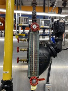
| Sight Glass and Moisture Indicators
|
A sight glass is installed in the liquid refrigerant to observe the liquid flow. It usually has one or two lenses. When the refrigerant level drops, the sight glass may show bubbles or foam instead of a clear, continuous flow of refrigerant. This indicates that there is insufficient refrigerant in the system, potentially due to a leak or a change in pressure.
The chemical dot under the sight glass, often referred to as a sight glass moisture indicator, functions similarly to a moisture indicator elsewhere in the system. It contains a desiccant that changes color upon exposure to moisture. When the refrigerant passes through the sight glass, any moisture present in the system is absorbed by the desiccant, causing the dot to change color. This color change serves as a visual indication to maintenance personnel that moisture may be present in the refrigerant, alerting them to potential issues with the system. |
| Heat Exchanger
|
A heat exchanger is used to transfer heat from the warm liquid flowing to the evaporator to the hot vapor that is taken from the evaporator. There are two advantages of using a heat exchanger:
|
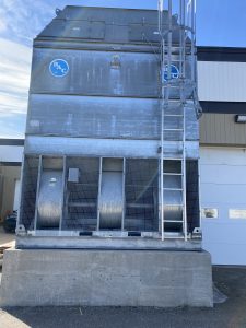
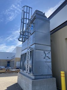
Cooling Towers
Definition: cooling towers are used to lower the temperature of the cooling water and equipment by using heat transfer.
Heat transfer occurs through two main processes: sensible heat transfer, which involves heating the air passing through the tower, and latent heat removal due to the evaporation of approximately 5% of the water. The evaporation process extracts additional heat from the remaining water.
Troubleshooting a Cooling Tower
The following troubleshooting guide is taken from PanGlobal under the Fair Use Policy.
| Trouble | Cause | Remedy |
| Excessive water drift |
|
2. Reduce water flow to tower to design conditions or use larger metering orifices. |
| Motor will not start |
|
2. Check motor and control connections against wiring diagrams. 3. Check nameplate voltage against power supply. Check voltage at motor terminals. 4. Check stator windings for open circuits. 5. Disconnect motor from load and check motor and gear reducer for cause of problems. 6. Look for broken bards and rings. |
| Unusual motor noise |
|
|
| Motor runs hot |
|
|
| Motor does not come up to speed |
|
|
| Wrong rotation (motor) |
|
|
| Gear reducer noise |
|
|
| Unusual fan drive vibration |
|
|
| Fan Noise |
|
|
| Scale or foreign substance in water |
|
|
| Wood deterioration |
|
|
Air Conditioning Systems
Air conditioning systems play a crucial role in maintaining good indoor air quality (IAQ) by ensuring a continuous supply of clean air that is free from contaminants.
Purpose: Air conditioning systems are engineered to uphold indoor conditions that ensure the comfort of occupants and support the intended purpose of the building.
Functional Components
| Heating |
|
| Cooling |
|
| Ventilation |
|
| Humidification |
|
| Dehumidification |
|
| Air Circulation |
|
| Filtration |
|
Operation
Air conditioning systems operate by removing heat and humidity from indoor air to create a comfortable and controlled environment. Here’s a simplified description of how they work:
- Air Intake: Warm air from the indoors is drawn into the air conditioning system through return air ducts.
- Filtration: Before reaching the main components, the air passes through filters to remove dust, pollen, and other particles, improving indoor air quality.
- Cooling: The air passes over a set of cold coils containing a refrigerant. The refrigerant absorbs heat from the air, causing it to cool down. This cooled air is then circulated back into the indoor space.
- Dehumidification: As the air cools, moisture in the air condenses on the cold coils. This removes humidity from the air, making it feel more comfortable.
- Exhaust: The heat absorbed by the refrigerant is expelled outside the building through a condenser coil, and the refrigerant is circulated back to the evaporator coil to repeat the cooling process.
- Thermostat Control: The temperature and humidity levels in the indoor space are monitored by a thermostat. Once the desired temperature is reached, the system cycles off until the temperature rises again.
Overall, air conditioning systems provide a controlled indoor environment by cooling and dehumidifying the air, maintaining comfortable temperature and humidity levels for occupants.
Copyright © 2017 PanGlobal. All rights reserved. Under Fair Use Policy.
PanGlobal. (2017). In Refrigeration. Low Pressure Boiler Components & Operation (2nd ed.). PanGlobal Training Systems Ltd.