15 Motors and Pumps
Motors and Pumps
Motors
Motor Action
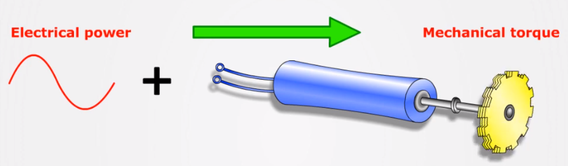
A motor converts electrical power into mechanical torque (motion). This is accomplished through the interaction of magnetic fields.
Two conditions are necessary to create mechanical torque (motor action). Current must flow through a wire conductor (which creates an electromagnetic field), and that conductor must be placed in an external magnetic field.
When a current flows through a wire, a circular magnetic field forms around the wire. The direction of the magnetic field depends on the direction of the current flow. This is important only because it will determine what direction the motor turns in.
You can predict the direction of the magnetic field by using the right hand rule. If the thumb of your right hand points in the direction of current flow in the magnetic field, the fingers will curl in the direction of the magnetic field. If the current is flowing in the opposite direction, the thumb will point in the opposite direction, and you will notice your fingers will curl in the opposite direction.
In the diagram below, the letter I represents current, and the letter B represents the magnetic field.
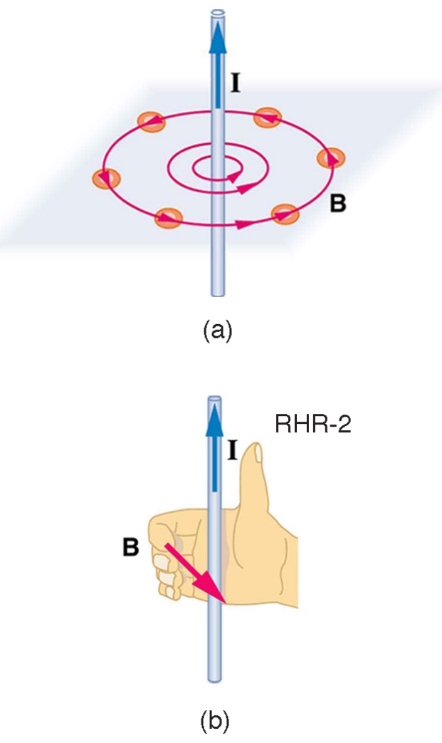
Image used under the CC BY 4.0 DEED license, available at https://commons.wikimedia.org/wiki/File:Openstax_college-physics_22.38_wire-Bfield.jpg
The conductor must be placed in an external magnetic field. When a conductor is placed between two magnets, the wire moves in one direction until it goes outside the magnetic field formed between the magnets (the external magnetic field.) The lines between the magnets are called magnetic flux lines and they represent a magnetic field called the main field.
The direction of the force that causes the wire to move depends on the direction the current flows through the conductor and the direction of the main field. In the diagram below the circle represents a conductor with current flowing in a direction out of the page. (What is not shown is the magnetic field created by the current in the conductor going in a counterclockwise direction. Get your right hand out and try it out yourself!)
The flux lines of the main field are basically straight in a north to south direction. However, the magnetic field created by the current in the conductor distorts the main magnetic field lines. In a way, the main magnetic field lines are bent, like elastic bands, and propel the conductor forward.
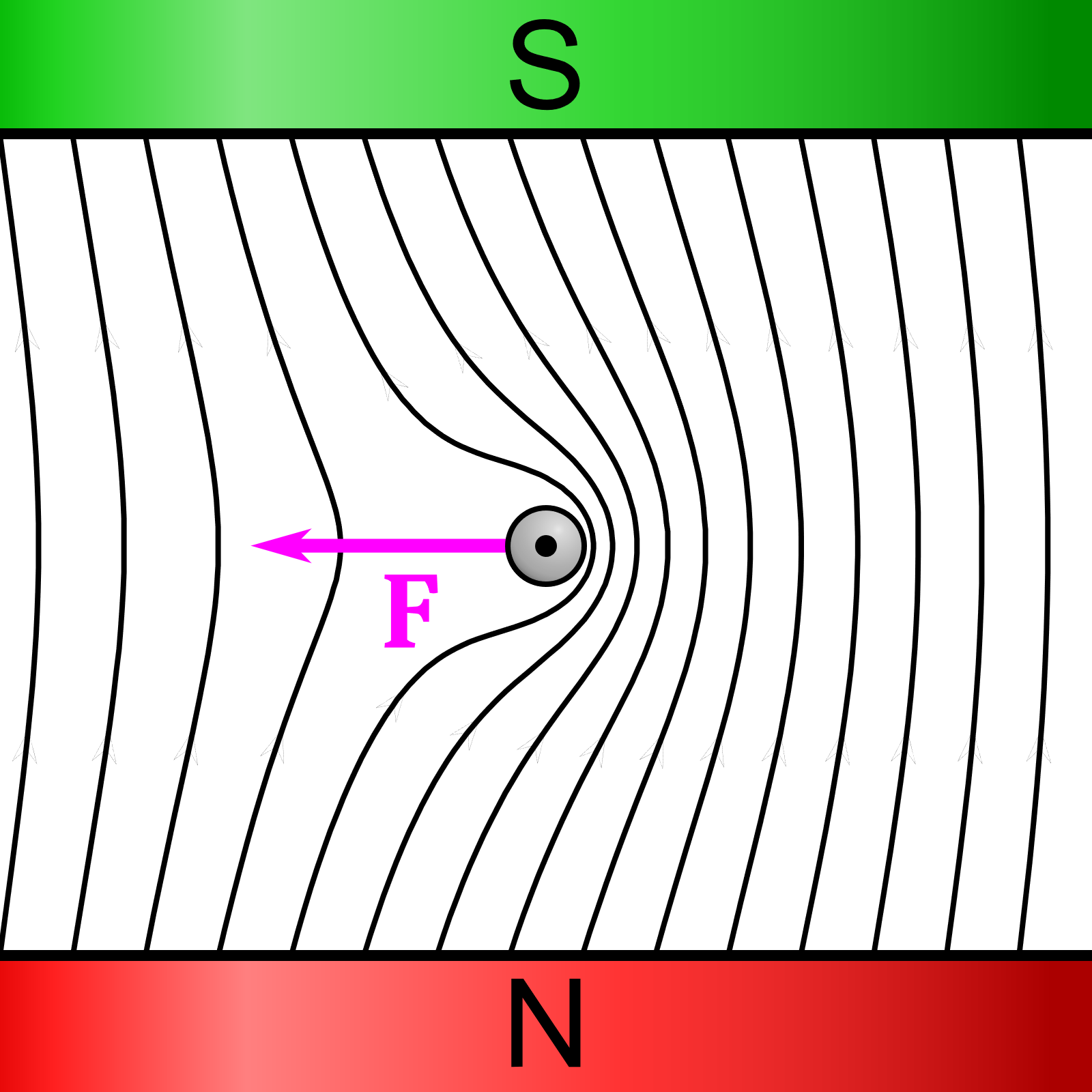
Image used under the CC BY 4.0 DEED license, available at https://commons.wikimedia.org/wiki/File:VFPt_wire-in-homogenous-magnetic-field-with-magnets-and-lorentz-force.svg
The direction the conductor moves in the magnetic field is ultimately the direction in which the motor will turn. This can be predicted by another right hand rule that considers the direction of the current in the conductor, and the direction of the external magnetic field. In the image below, if you point your thumb in the direction of the current (I), and your forefinger in the direction of the external magnetic field (B), the conductor will experience a force (F) in the direction of your index finger.
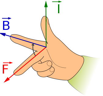
Image used under the CC BY 4.0 DEED license, available at https://commons.wikimedia.org/wiki/File:Rechte-Hand-Regel.svg
Watch the following video on motor action.
https://www.youtube.com/watch?v=onjFFoOC_yk&list=PL85IZwEbljsfI_fl-Ri6_Yxr4hNiNFg__&index=2
Information for this section was adapted from https://www.wisc-online.com/learn/technical/industrial-automation/iau18319/motor-action-screencast#google_vignette under a Creative Commons Attribution-NonCommercial 4.0 International License.
Fundamentals of a motor
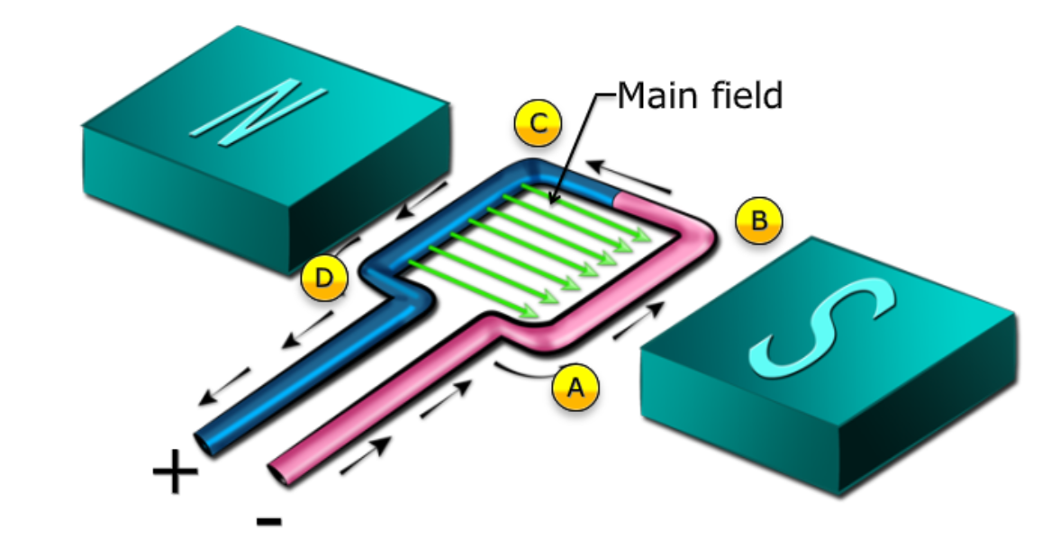
We talked about a conductor moving in one direction through a magnetic field. However, a motor produces a continuous twisting motion. The conductor that is placed inside of the main field, between the two magnets, is in the shape of a loop. When the loop is connected to a DC power supply, current flows from point A, to B, to C, and D. Notice that when the current enters the loop it is going in one direction through the main field. When the current exits the loop, it is flowing in the opposite direction. We have learned (from the right hand rule) that a change in direction of the current will change the direction of the force on the loop from the main field.
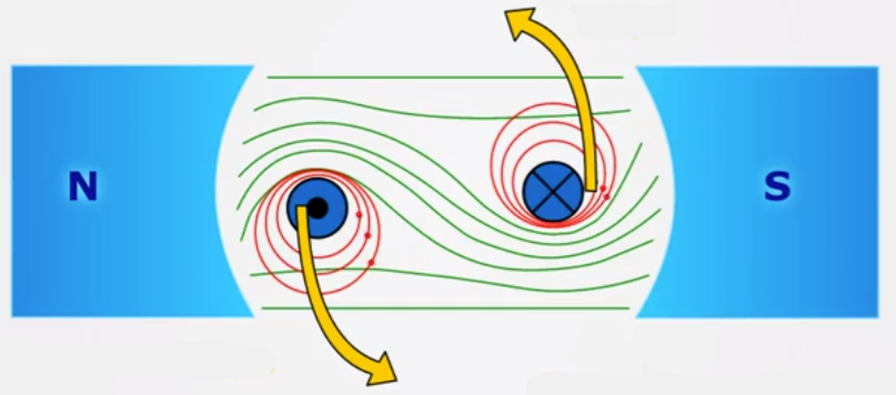
Because current flows through the segments of the loop that are opposite each other, the segment on one side pushes upward while the segment on the other side pushes downward. This combined force creates a twisting motion called torque. In the following diagram, we are looking end-on at the loop conductor. On the left side, the current is coming out of the page, and on the right side the current is going into the page.
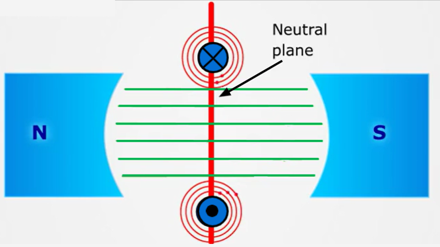
When the loop rotates to an up and down position (called the neutral plane) there are two problems: The magnetic field provides no force in the neutral position. Secondly, to continue twisting in the same direction, the direction of current needs to flip. (Otherwise, the loop would just swing back and forth.)
Additional explanation: the reason the current needs to flip is to change the direction of the force. In the diagram above, the right side of the loop is being pushed up through the main field. When it crosses the neutral plan, that same part of the loop needs to be pushed down. The direction of force needs to change so the current needs to change direction.
The solution to the first problem (no force in the neutral position) is that the momentum of the loop rotating carries it over the neutral plane where there is no force. That being said, when the motor is first starting and there is no momentum, there needs to be an additional “kick” to get the loop over the neutral plane- that won’t be discussed now.
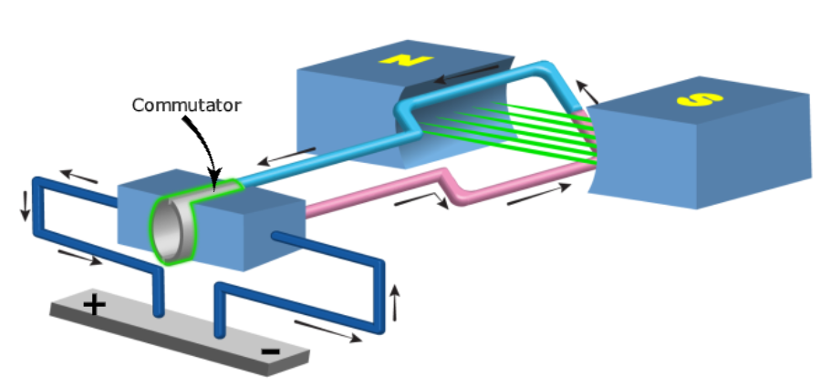
Overcoming the second problem (the current needs to flip direction) is done by introducing a commutator at the end of the loop.
The commutator is shaped like a ring that is split into two segments. Each segment is connected to the power supply through a carbon ‘brush’ that rubs against the commutator. The commutator and loop rotate together and are together referred to as the armature.
As the armature turns, the commutator makes contact with the carbon brushes that supply current to the wire loop. Each brush is connected to a DC power supply (like a battery). In the diagram below, the segment on the right is connected to the negative side of the power supply. As the armature rotates counter clockwise past the neutral plane, the same segment will become connected to the positive side of the power supply and as a result the current direction is switched.
In reality, there are many loops at all angles around an entire circle (called the winding). The following picture shows an actual armature from a motor. Each loop has its own segment (top and bottom) on the commutator.
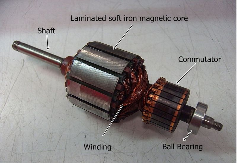
Image used under the CC0 1.0 Universal Public Domain license and is available at https://commons.wikimedia.org/wiki/File:Motor_rotor.jpg
Information for this section was adapted from https://www.wisc-online.com/learn/technical/electronics-dc/dce17115/fundamentals-of-a-dc-motor under a CC BY 3.0 DEED License.
There are many types of motors, some using direct current (as described above), some using alternating current, and some using three phase power. The most powerful industrial motors will use three phase power, but a lot of the basics are the same as above. In the next section we will talk about what motors might be used for in your workplace.
Motor Application: Fans
One application of electric motors is in the operation of fans for ventilation.
Sometimes called the air-handler unit or the blower, the fan is the device which drives the treated air throughout the building. Usually driven by a single-phase AC motor in smaller applications, and a three-phase motor in larger commercial or industrial applications.
There are two main categories of fans, each with their own advantages and applications: the axial fan, which draws air parallel to the rotating axis and the centrifugal fan, which draws air at a right angle to its rotating axis.
Axial Fan
Axial fans are designed for moving low volumes of air under low static pressure conditions.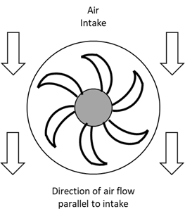
In their most basic shape an axial fan resembles an airplanes propeller, and simple household fans utilize this design.
While the propeller design is the simplest, there are other styles of axial fans. The tubeaxial, which is simply propeller-style blades installed in a ducting tube to help direct and focus air flow, and the vaneaxial, which incorporates air straightening vanes down behind the blades, and boasts the highest efficiency of the axial fans.
Due to their lower power requirements, axial fans are usually powered by single-phase AC motors which are either driven directly or via a belt system. They are generally quiet in operation and are favoured in places where noise levels are a factor but are not suitable for moving large volumes of air.
These styles of fans are often used to drive fresh air over the condenser coils in rooftop units of air conditioning systems.
Centrifugal Fans
Centrifugal fans are better suited to push larger volumes of air through ducting systems. They are designed to produce higher pressure for a given volume of air than an axial fan of the same horsepower rating. Any fan used to drive air throughout the system must produce enough total pressure to overcome the static pressure of the ducting system and drive air everywhere it is needed.
A centrifugal fan has the direction of air flow perpendicular to the air intake.
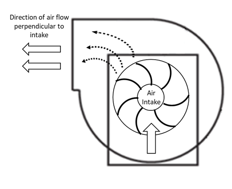
Drawing the intake air at 90 degrees relative to the outtake, the fan blades direct the air in an spinning, circular direction, accelerating it towards the exhaust vent.
Depending upon the application, the drive mechanism of the fan may be directly coupled, belt driven, or powered by a variable speed drive.
Centrifugal fans are noisier than an axial fan of equivalent horsepower, and so are often installed in areas where high noise levels are acceptable, or noise dampening components can be installed.
Centrifugal fans can move large quantities of air, while overcoming all the resistive static pressure of the duct-work system.
Fan Substitutions
There are three important considerations to keep in mind when changing the motors of HVAC fans, if a change in speed or horsepower is also involved.
The first is that airflow varies directly with fan speed, so doubling the speed of the fan will double the airflow.
Fan Speed = Air Flow
The second is that static pressure varies with the square of the fan speed, so that doubling the fan speed will quadruple the static pressure in the ductwork.
Fan Speed = (Static Pressure)2
The third consideration is that electrical power consumed by the motor varies with the cube of the fan speed, so that it requires a motor with eight-times the horsepower rating of the previous motor to double the fan speed.
Fan Speed = (Power Consumed)3
This will result in a very significant change in the demand of the electrical draw of the motor. Be sure not to exceed the current, voltage, or horsepower ratings of any electrical circuits, or overcurrent devices.
Glossary Terms
Blower: A motor that drives air in force-air systems.
Axial fan: Axial fans drive low volumes of air under low static pressure conditions in parallel with their axis of rotation. Mainly used for cooling of coils.
Centrifugal fan: A centrifugal fan drives lager volumes of air under high static pressure conditions at a right angle to its axis of rotation. Mainly used for the moving air through ductwork.
Total pressure: The sum of static and velocity pressure that must be overcome by an air handling unit.
Static pressure: The force resisting the movement of air.
References
This material has been adapted from the following sources
BCcampus, Basic HVAC, available at https://opentextbc.ca/basichvac/ used under the license CC BY 4.0 DEED
Motor Application: Compressors
In heating, ventilation, and air conditioning (HVAC) systems, electrical compressors play a pivotal role in regulating temperature, humidity, and air quality within buildings. These compressors are responsible for circulating refrigerant through the system, enabling the transfer of heat between indoor and outdoor environments. This article explores the significance of electrical compressors in HVAC applications, their types, functions, and key considerations.
Types of Electrical Compressors
Reciprocating Compressors: Reciprocating compressors use pistons driven by an electric motor to compress refrigerant gas. They are commonly found in smaller HVAC systems and are known for their simplicity, reliability, and cost-effectiveness.
Scroll Compressors: Scroll compressors employ spiral-shaped scrolls to compress refrigerant. They offer smooth and quiet operation, making them suitable for residential and light commercial HVAC applications.
Rotary Compressors: Rotary compressors use a rotating shaft with vanes to compress refrigerant gas. They are compact, efficient, and often utilized in ductless mini-split systems and packaged air conditioning units.
Functions of Electrical Compressors in HVAC
Refrigerant Compression: The primary function of electrical compressors in HVAC systems is to compress low-pressure refrigerant gas into high-pressure gas, enabling heat transfer and the refrigeration cycle.
Heat Exchange: Compressors facilitate the transfer of heat between the indoor and outdoor environments by circulating refrigerant through the evaporator and condenser coils.
Temperature Regulation: By adjusting the compression ratio and refrigerant flow rate, compressors help maintain desired indoor temperatures, contributing to occupant comfort and energy efficiency.
Key Considerations
System Capacity: Selecting the appropriate compressor size and capacity is essential to meet the cooling demands of the HVAC system while ensuring efficient operation and temperature control.
Energy Efficiency: Energy-efficient compressors can significantly reduce operating costs and environmental impact. Variable-speed compressors, inverter-driven compressors, and scroll compressors with modulation capabilities offer enhanced efficiency by adjusting output according to load demand.
Reliability and Maintenance: Opting for compressors from reputable manufacturers and implementing regular maintenance schedules are crucial for ensuring reliable operation and minimizing downtime in HVAC applications.
Noise Levels: Noise emissions from compressors can impact occupant comfort, particularly in residential and commercial settings. Selecting compressors with low noise levels or incorporating sound-dampening measures can mitigate this issue.
References
McQuiston, Faye C., et al. Heating, Ventilating, and Air Conditioning: Analysis and Design. Wiley, 2017.
Brumbaugh, James E. Audel HVAC Fundamentals, Volume 1: Heating Systems, Furnaces, and Boilers. Wiley, 2004.
Motor Application: Pumps
Electrical Pumps for HVAC Applications
In heating, ventilation, and air conditioning (HVAC) systems, electrical pumps play a vital role in circulating fluids, typically water or a water-glycol mixture, to facilitate the transfer of heat or cool air throughout a building. These pumps are essential components in maintaining optimal indoor climate control and energy efficiency. This article explores the significance of electrical pumps in HVAC applications, their types, functions, and key considerations.
Types of Electrical Pumps
Centrifugal Pumps: Widely used in HVAC systems, centrifugal pumps utilize centrifugal force to increase the fluid’s velocity and create pressure. They are efficient for moving large volumes of water at relatively low pressures.
Reciprocating Pumps: These pumps use pistons or diaphragms to create pressure differentials, pushing fluid through the system. While they can produce high pressures, they are less common in HVAC applications due to their higher maintenance requirements.
Rotary Pumps: Rotary pumps, such as gear pumps and screw pumps, are used in HVAC systems for their ability to provide a steady flow of fluid with minimal pulsation. They are suitable for applications requiring precise control and constant flow rates.
Functions of Electrical Pumps in HVAC
Fluid Circulation: Electrical pumps circulate water or coolant throughout HVAC systems, facilitating heat transfer between various components such as boilers, chillers, and air handling units.
Pressure Maintenance: Pumps maintain the required pressure levels within the system to ensure efficient operation of heat exchangers, coils, and other HVAC components.
Temperature Control: By controlling the flow rate of the fluid, pumps assist in regulating the temperature of air or water in the HVAC system, contributing to comfort and energy efficiency.
Key Considerations
Energy Efficiency: Selecting energy-efficient pumps can significantly reduce operational costs and environmental impact. Variable speed drives (VSDs) are often employed to modulate pump speed according to system demand, optimizing energy consumption.
Reliability: Reliability is crucial in HVAC applications to avoid downtime and maintain indoor comfort. Choosing pumps from reputable manufacturers and implementing regular maintenance schedules are essential for ensuring reliable operation.
System Compatibility: Pumps must be compatible with the specific requirements and configurations of the HVAC system they serve. Factors such as flow rate, pressure, and fluid properties should be carefully considered during pump selection.
Noise Levels: Noise generated by pumps can affect occupant comfort, particularly in residential or commercial spaces. Selecting pumps with low noise levels or implementing noise-reduction measures can mitigate this issue.
Electrical Pump Maintenance for HVAC Applications
Maintenance of electrical pumps in HVAC systems is crucial for ensuring reliable operation, energy efficiency, and longevity of the equipment. Regular maintenance routines help prevent breakdowns, reduce energy consumption, and extend the lifespan of pumps. Here are key aspects of electrical pump maintenance in HVAC applications:
Inspection and Cleaning: Regular inspections of pump components such as impellers, bearings, seals, and motor connections are essential. Any debris or buildup should be promptly removed to prevent clogging and reduce strain on the pump motor.
Lubrication: Proper lubrication of pump bearings is vital for reducing friction and wear. Lubricant levels should be checked regularly, and bearings should be greased according to manufacturer recommendations to ensure smooth operation.
Alignment and Balance: Misalignment of pump shafts can lead to excessive vibration and premature wear of bearings and seals. Periodic alignment checks and adjustments are necessary to maintain optimal performance and prevent damage to pump components.
Pump Motor Maintenance: Electrical components such as motor windings, capacitors, and wiring should be inspected for signs of wear or damage. Motor connections should be tightened, and any electrical issues should be addressed promptly to prevent motor failure.
Performance Monitoring: Monitoring pump performance parameters such as flow rate, pressure, and power consumption can help identify potential issues early on. Any deviations from normal operating conditions should be investigated and rectified to prevent further damage.
System Flushing and Fluid Replacement: Flushing the HVAC system and replacing fluids at recommended intervals help remove contaminants and maintain fluid quality. This prevents corrosion and scale buildup, which can affect pump performance and efficiency.
Safety Checks: Safety features such as pressure relief valves, temperature sensors, and overload protection should be inspected regularly to ensure they are functioning correctly and provide adequate protection against potential hazards.
Regular maintenance of electrical pumps in HVAC systems is essential for maximizing performance, minimizing downtime, and ensuring occupant comfort and safety.
References:
Silvestri, Mark. HVAC Pump Handbook. McGraw-Hill Education, 2019.
Brumbaugh, James E. Audel HVAC Fundamentals, Volume 2: Heating System Components, Gas and Oil Burners, and Automatic Controls. Wiley, 2004.
McQuiston, Faye C., et al. Heating, Ventilating, and Air Conditioning: Analysis and Design. Wiley, 2017.
Bell, Geoffrey, et al. HVAC Water Chillers and Cooling Towers: Fundamentals, Application, and Operation. CRC Press, 2018.