63 Ignition Systems
Learning Objectives
Outcomes: Describe components and function of ignition systems
Key Questions: How does a small engine start?
Learning tasks: Read course material
Topics: Points and condenser, electronic ignition, spark plugs
Assessment: online quiz
Estimated Time: 1.5 hours
About the Ignition System
The ignition system is responsible for starting the engine. It supplies high voltage to the spark plugs when the piston is near the top of its compression stroke to explode the air-fuel mixture in each cylinder.
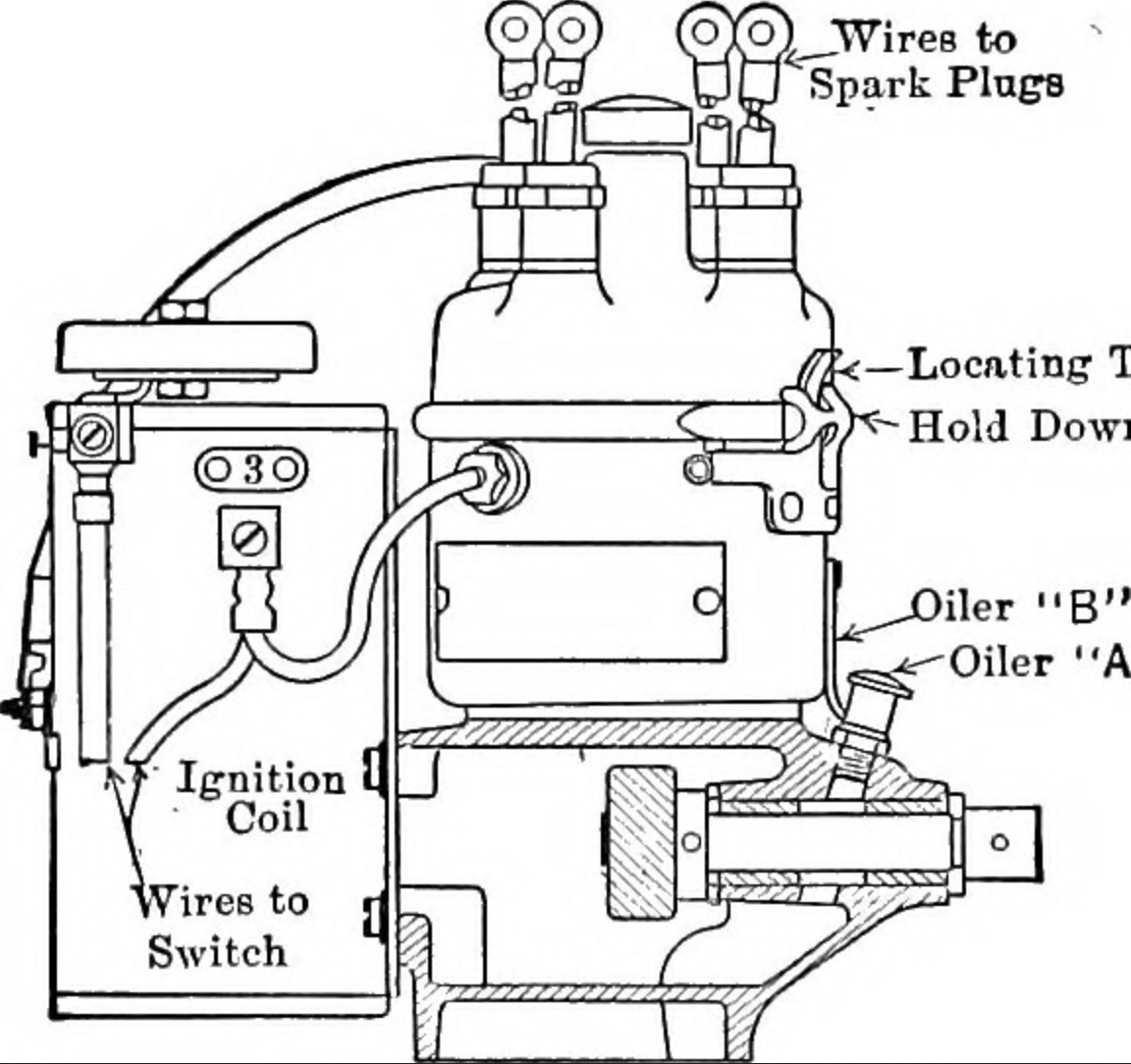
The ignition system is made up of the ignition coil, a spark plug, a distributor/ignition module, the ignition switch, and the timing mechanism.
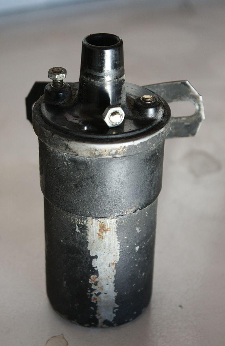
The ignition coil is responsible for taking the low voltage from the battery and turning it into the high voltage needed to create the spark. Ignition coils have two sets of wire windings. The primary wire winding receives the low voltage from the battery and creates a magnetic field. This magnetic field induces a higher voltage in the second wire winding which creates the spark.
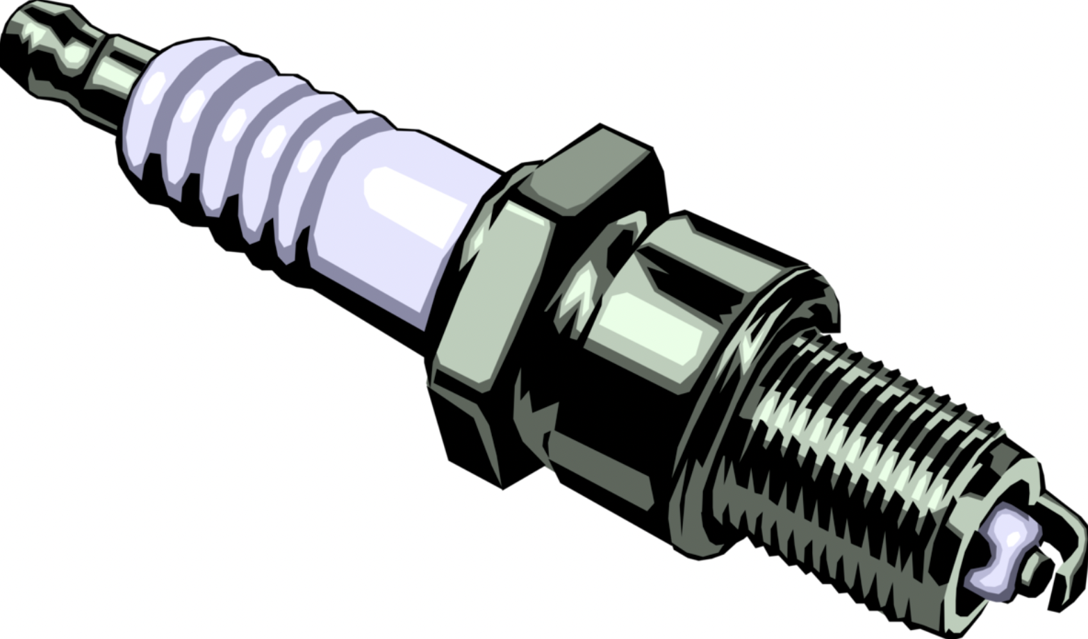
The spark plug carries electricity down its center electrode, which is insulated by a ceramic collar. The current jumps the small gap between electrodes, creating the spark that ignites the fuel. Spark plugs should be checked every 50 operating hours. If the electrodes are not worn, the spark plug can be cleaned and returned. If the electrodes are rounded, the plug needs to be replaced.
The heart of the system is the distributor. In older ignition systems, a distributor is used to distribute the high voltage from the ignition coil to each spark plug in the correct firing order. Each time the breaker points in the distributor are opened, the 12-V electricity flowing through the coil is stepped up to 20,000 V or more. This high voltage is returned to the center of the distributor cap by a heavy cable. A rotor, spinning just under the cap, distributes this current in proper sequence to a series of heavy cables. One cable leads to each spark plug. When the current reaches the plug, it jumps a gap between two small prongs igniting the fuel mixture in the cylinder. The current then returns to the battery through the engine block and frame, completing the circuit. This high voltage will seek the path of least resistance back to the battery.
In more modern engines, an ignition module may be used instead of the distributor. Ignition modules receive signals from the engine’s sensors to determine when to ignite the spark.
The ignition switch is operated by a key, like when you start your vehicle. It activates the ignition system and starts the engine. When the key is turned, it sends power from the battery to the ignition system.
Lastly, the timing mechanism within the ignition system makes sure that the spark occurs at the correct position of the piston.
When the ignition switch is turned, current flows from the battery to the ignition coil. When the timing mechanism determines that the piston is at the top of the compression stroke, it notifies the ignition coil to convert the low voltage from the battery into the necessary high-voltage pulse. This pulse is sent to the spark plug through the distributor or ignition module. The spark plug ignites the fuel in the combustion chamber, and this starts the engine.
Vehicle ignition systems: https://www.youtube.com/watch?v=dIQ4IWSpMO0 (7 min)
 |
 |
General Maintenance of the Ignition System
If the ignition cables, distributor cap, or coil are cracked, wet, or dirty, current may leak out of them causing a weak spark or no spark at all. Loose or corroded connections in the system will have the same effect. If you experience starting or stalling problems, clean and dry all the cables and spray them with a waterproofing silicone aerosol.
Pull each cable from its terminal (one at a time to prevent mixups), use a penknife or wire brush to remove any corrosion, and then push the cable firmly home. If the system becomes soaked with rainwater, it may not work. Dry the cables, the top of the coil, and the inside of the distributor cap with a dry, lint-free towel or a special water-repellent spray made for this purpose and sold in an auto parts store.
Maintenance of spark plugs includes inspecting them for corrosion and wear, and cleaning or replacing them as needed. You can use a spark plug gap gauge to make sure the gap between the electrodes is correct. It is important to make sure that the timing is set properly. Sometimes timing adjustments must be made to keep the ignition system functioning properly. Ignition coils and wires must be checked for damage and corrosion as well. If damage is found, they must be replaced.
Other parts of the ignition system that must be inspected for damage and potentially replaced are the distributor cap and rotor, the ignition switch, and/or the ignition module. The manufacturer’s maintenance schedule will have recommendations for service and inspections. Cleaning and lubricating moving parts will keep the ignition system running smoothly. Lastly, an important part of ignition system maintenance is checking the battery voltage and connections as well as inspecting grounding connections. Poor connections can cause weak sparks and impact the efficiency of the ignition systems.
Points and Condenser
Points and condensers, also known as contact breaker points and capacitor discharge ignition (CDI) condensers, are components of traditional ignition systems used in older vehicles and small engines before electronic ignition systems became the standard. Points and condensers are no longer common in modern vehicles.
The breaker points act as a switch that sends current to the spark plug at the right moment. It interrupts the flow of current to the ignition coil, causing the high-voltage spark. Breaker points are made of two metal contacts located on a cam follower. One of these contacts is connected to the ignition coil, and the other one is grounded to the engine block. The cam follower is initiated by the camshaft or distributor cam. During engine operation, the points are closed when the cam follower is in contact with the high point on the camshaft or distributor cam. This allows current to flow from the ignition coil to the points, charging the ignition coil’s primary winding. As the camshaft rotates, the cam follower moves away from the high point, causing the points to open. This interrupts the flow of current to the ignition coil, causing a rapid collapse of the magnetic field and inducing a high-voltage spark at the spark plug.
The points should be adjusted or replaced periodically, using a kit available at most hardware stores. You must remove the flywheel to reach the points on most engines. On a few models the points are reached through an access panel on the block; check the owner’s manual. To work properly, the gap between the fully opened points must be set at a specified distance, measured to within 1/1000 inch. This is done with a feeler gauge- a set of metal blades of precise thickness, sold in auto parts stores. The condenser is customarily replaced at the same time as the points.
Condensers are used to suppress arcing across the points. This helps to prolong the lifespan and reliable ignition timing. Condensers are small cylinders located near the points. They are made up of two conductive plates separated by a dielectric material like paper or ceramic. The condenser is connected parallel to the points. They help to prevent arcing my storing and releasing electrical energy. They do this by absorbing and dissipating the electrical energy made by the collapsing magnetic field. This then suppresses the arc across the points and prevents damage to the ignition system.
Points and condensers: https://www.youtube.com/watch?v=gZgZuqX3yKY (1 min)
Electronic Ignition
A growing number of engine manufacturers are replacing the points and condenser with an electronic module mounted next to the flywheel. This is because electronic ignition systems are more reliable and efficient. The components of the electronic ignition system include:
- the ignition control module (ICM),
- the crankshaft position sensor (CKP),
- the camshaft position sensor (CMP),
- the ignition coil, and the engine control module (ECM).
The ICM controls the timing and duration of the ignition spark based on input from the engine’s sensors. The ICM gets information from the CKP for ignition timing. The CKP sensor also detects the position and speed of the crankshaft. In engines with overhead camshafts, the CMP sensor detects the position of the camshaft, helping to determine ignition timing. The ignition coil in electronic ignition systems functions similarly to those in traditional systems, converting low-voltage electrical signals from the ICM into high-voltage sparks. In some ignition systems, the ECM serves as the central control unit for engine operation.
The electronic ignition system operates by using input from engine sensors to control the timing of the ignition spark. The CKP and CMP sensors provide data on the positions of the crankshaft and camshaft to the ICM or ECM. Based on the input, the ICM or ECM calculates the timing for the ignition and signals the ignition coil to ignite the spark. The ignition coil produces high-voltage sparks to ignite the fuel in the combustion chambers.
Electronic ignition systems systems are more reliable, resulting in easier engine starting and smoother operation.
When it comes to electronic ignition maintenance- if the module malfunctions, it is replaced as a unit. Buy the replacement before replacing the faulty unit, if possible. You can install a new ignition module in the same manner as the old one. Tighten screws only part way, so that the module is free to move in its elongated mounting slots. Rotate the flywheel until its magnets are fencing the module. Place the feeler blade or post card on top of the magnets and push the module gently toward the flywheel. The magnets should draw the module toward your gauge and hold it in position while you tighten the screws.
Electronic ignition vs points and condenser: https://www.youtube.com/watch?v=qFDeWP91fN4 (12 min)
References
Dixon, John. “The Complete Guide to Small Engine Repair.” Cool Springs Press, 2009.
Demorro, Kevin. “Small Engine Repair: 5.5 HP Through 20 HP Four Stroke Engines.” Independently Published, 2019.
Clarke, Tim. “How to Repair Briggs and Stratton Engines.” CreateSpace Independent Publishing Platform, 2010.
“Automotive Ignition Systems” by Tony Candela. CarTech Books, 2009.
“How to Repair Briggs and Stratton Engines” by Tim Clarke. CreateSpace Independent Publishing Platform, 2010.
“Automotive Technology: Principles, Diagnosis, and Service” by James D. Halderman. Pearson, 2018. “Small Engine Repair: 5.5 HP Through 20 HP Four-Stroke Engines” by Kevin Demorro. Independently Published, 2019.