57 Heating Systems and Human Comfort
Learning Objectives
- Describe sources of heat gain and loss
- Define heat transmission terminology
- Describe the construction, operation, and maintenance of various heating systems
- Describe recommended maintenance procedures for warm air heating systems
- Troubleshoot forced warm air systems and components
Essential Questions
- Why is heat lost or gained in a building?
- How can heating systems be maintained to ensure peak efficiency?
Introduction
Heating modern buildings is one of the most important functions that HVAC systems can provide. The energy required to heat a space, or a house comes from either the burning of natural gas, or it comes from electric heating loads. The method of distributing heat throughout a building can also vary, depending on the medium used to transport the heat. Usually forced air or water is used, though some heating loads, such as baseboard heaters, rely on passive heat dissipation.
Heat Gain
Heat gain in commercial HVAC refers to the increase in thermal energy within a building’s interior spaces due to various factors such as solar radiation, heat transfer through building envelopes (walls, roofs, windows), internal heat sources (occupants, lighting, equipment), and outdoor air infiltration. It is a critical consideration in HVAC system design and operation, as excessive heat gain can lead to discomfort, reduced indoor air quality, and increased energy consumption for cooling. Effective management of heat gain involves proper insulation, shading strategies, efficient building envelope design, and the selection of appropriate HVAC equipment to maintain comfortable and energy-efficient indoor environments.
Sources
Conduction
Conduction is the process by which heat energy is transferred through solid materials from areas of higher temperature to areas of lower temperature. In commercial HVAC systems, conduction contributes to heat gain when heat flows from warmer external environments into the interior spaces of buildings. This occurs through various pathways, including windows, doors, walls, roofs, and building materials.
For example, during hot weather, sunlight can heat up windows and doors, causing them to conduct heat into the building’s interior. Similarly, external walls and roofs can absorb heat from the sun and transfer it into the building through conduction, especially if they lack adequate insulation. Additionally, materials commonly used in construction, such as concrete, metal, and glass, can conduct heat from the outside environment into the building’s interior.
Furthermore, HVAC equipment located outside or in unconditioned spaces can absorb heat from the surrounding air and transfer it into the building through conduction. Overall, conduction plays a significant role in heat gain in commercial HVAC systems by allowing heat to flow through solid materials, thereby increasing the demand for cooling to maintain comfortable indoor temperatures.
Infiltration
Infiltration occurs when outdoor air seeps into a building through cracks, gaps, or other openings in the structure. This uncontrolled airflow can introduce heat into the building, contributing to heat gain in commercial HVAC systems. When warm outdoor air enters the building, it raises the indoor temperature, making it more challenging for the HVAC system to maintain comfortable conditions. Additionally, sunlight can also penetrate through these openings, adding solar radiation and further increasing heat gain. Infiltration may also bring humidity indoors, which can exacerbate the discomfort and strain on the HVAC system. To mitigate heat gain from infiltration, it’s crucial to seal and insulate the building envelope effectively to minimize the uncontrolled flow of outdoor air into the conditioned spaces.
Infiltration or ventilation load refers to the amount of heat or cooling required to maintain indoor air quality and comfort levels in a building due to the exchange of air with the outdoor environment. This load encompasses the energy needed to compensate for the infiltration of outdoor air into the building and the ventilation requirements necessary to remove contaminants and maintain acceptable air quality. Managing infiltration and ventilation loads is crucial for ensuring efficient HVAC system operation and indoor comfort while minimizing energy consumption and operating costs.
Ventilation
Ventilation in commercial HVAC systems introduces outdoor air into the building to maintain indoor air quality and provide fresh air for occupants. However, this process can lead to heat gain through two main mechanisms:
- Outdoor Air Temperature: If the outdoor air temperature is higher than the desired indoor temperature, bringing it into the building during ventilation can raise the overall temperature inside. The HVAC system then needs to expend energy to cool down the warmer air, resulting in heat gain.
- Humidity: Outdoor air often contains moisture, especially in humid climates. When this humid air enters the building through ventilation, it increases the indoor humidity levels. Higher humidity can make indoor spaces feel warmer, prompting occupants to demand more cooling from the HVAC system. As a result, the system works harder to remove moisture and maintain comfort, leading to additional heat gain.
It is preferable to use this source rather than infiltration, as ventilation provides a constant, steady, and controlled input of air.
Radiation
Radiation causes heat gain in commercial HVAC systems through the transfer of thermal energy from warm surfaces to cooler surfaces without the need for direct contact or an intervening medium. This phenomenon occurs in three primary ways:
- Solar Radiation: Sunlight enters the building through windows, skylights, or other transparent surfaces, heating up interior surfaces such as walls, floors, and furniture. These heated surfaces then radiate thermal energy into the surrounding air, increasing the overall temperature inside the building and leading to heat gain.
- Internal Heat Sources: Equipment, lighting fixtures, electronic devices, and even occupants within the building generate heat. This heat is emitted in the form of infrared radiation, which can be absorbed by nearby surfaces, causing them to warm up and contribute to the overall heat gain in the space.
- Thermal Radiation Between Surfaces: Surfaces within the building, such as walls, ceilings, and floors, exchange radiant heat energy with each other based on their temperatures and emissivity properties. Warmer surfaces radiate heat to cooler surfaces, resulting in a net transfer of thermal energy and potential heat gain in areas where it is not desired.
Overall, radiation contributes to heat gain in commercial HVAC systems by transferring thermal energy from warm surfaces to cooler ones through electromagnetic waves, thereby increasing the temperature of the indoor environment. Effective strategies for mitigating radiation-induced heat gain include using shading devices, reflective surfaces, and insulation to minimize solar heat gain and optimizing the layout and operation of internal heat sources to reduce unnecessary heat generation.
Heat Loss
Heat loss in commercial HVAC systems is the process by which thermal energy escapes from the building’s interior to the outside environment, leading to a decrease in indoor temperature. This phenomenon can occur through several mechanisms, including conduction, where heat transfers through solid materials like walls and windows, convection, where heat is carried away by air currents, and radiation, where heat is emitted as infrared energy. Effective insulation and sealing of building envelopes are crucial in minimizing heat loss and maintaining indoor comfort levels while maximizing energy efficiency.
Sources
Conduction, Convection, and Radiation
Heat moves through building walls, ceilings, and floors from warmer internal surfaces to cooler external ones, facilitated by conduction. As warm room air near outer walls and ceilings loses heat, it becomes denser, descends, and is replaced by warmer air, creating convection currents that contribute to heat loss. Additionally, warmer objects and surfaces emit heat through radiation towards colder outside walls or windows. A practical example is feeling cold when standing close to an exterior wall or window in winter, as heat radiates from your body to the cooler surface. These heat losses can be mitigated by enhancing insulation, such as adding layers of materials like fiberglass or Styrofoam to walls, and by installing multiple panes of glass in windows. Double-pane windows, particularly those filled with argon gas, significantly reduce heat loss compared to single-pane windows. For instance, a single-pane window with an outside temperature of -18°C (0°F) and an indoor temperature of 21°C (70°F) would have a glass temperature of -9°C (16°F). In contrast, a double-pane window with argon gas would maintain an inside glass temperature of 13°C (55°F), approximately 22°C (40°F) warmer.
Infiltration
Buildings also experience heat loss due to air leakage, referred to as infiltration. This occurs primarily around windows and doors and, in poorly constructed buildings, to some extent through walls. When cold air infiltrates a building, it needs to be heated by the heating system, leading to increased fuel consumption. Conversely, warm air may escape from the building as well.
To mitigate infiltration, it’s important to thoroughly seal around window and door frames using caulking and employ weatherstripping techniques.
Calculation Example:
Steam Heating Equipment and Systems
Steam heating involves the production of steam in a centralized boiler. This steam is then distributed throughout the building via pipes connected to radiators, convectors, and unit heaters. As the steam moves through the system, it releases its latent heat within these heating devices, causing it to condense back into liquid form. The resulting liquid, known as condensate, returns to the boiler where it is reheated and converted back into steam. In contrast, hydronic (hot water) and warm air heating systems are more commonly used in residential and smaller commercial buildings. Steam heating, however, is often preferred for larger structures like hospitals and factories due to its efficiency. Over time, various types of steam heating systems have been developed, each consisting of numerous components referred to as auxiliary equipment. It is important for power engineers to be familiar with these components and understand their respective functions within the steam heating system.
Equipment
| Radiators | Radiators are designed to maximize the surface area available for transferring heat from the steam or hot water within the radiator to the air in the surrounding space. Traditionally, radiators were constructed using cast iron and consisted of interconnected sections joined by screw or push nipples.
In contrast, contemporary radiators are fabricated from lightweight steel pressings that are welded together. Not only are these modern radiators more visually appealing and contemporary, but they are also significantly lighter in weight. Radiators are categorized into floor type, which are equipped with legs to stand on the floor, window type, suitable for installation beneath windows where space is limited, and wall-hung radiators, which do not require legs and can be mounted directly onto walls. |
| Convectors | Convectors have become the preferred choice overcast-iron radiators in contemporary setups. These units feature a copper or steel tube through which steam or hot water flows. Metal fins are affixed to the tube to enhance heat transfer from the tube to the air circulating within the convector. The heating piping is encased within a metal cabinet cover, which includes grill-type openings at the top and an open bottom. |
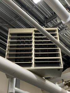
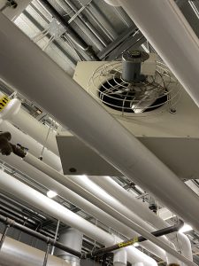
| Unit Heaters | Unit heaters are often installed at ceiling height or recessed into a wall, and consist of a heating element, a built-in blower fan and louvers to direct the direction of heated airflow. They are small and compact in size yet have a high capacity for heating a room or area.
If a single unit heater is to be installed, its heated airflow should be directed towards the area of highest ambient heat loss, such as a window or door, however care should be taken to make sure that no surface is heated beyond a safe level. If multiple unit heaters are installed their air flow should be directed in a circular motion along the exposed outer walls. Control of unit heaters is similar to that of baseboard heaters, in that there must be a temperature activated switch, either installed directly on the heater unit, or more effectively, in another part of the room. A built-in fan switch is also provided to allow the fan to circulate air during warm weather without energizing the heater elements. Unit heaters are available anywhere from 2 kW to 60 kW, with units on the lower side, up to approximately 5 kW usually being single-phase AC and controlled by low-voltage thermostats and relays, while units rated above 5 kW are usually three-phase. |
| Fon Coils/Reheat Coils | In bigger structures, air for heating is frequently extracted from the rooms using a fan and directed through a network of ducts to a central location. There, the air is pushed through a fin coil or reheat coil, which is heated by steam or hot water and positioned across the air duct. This coil typically comprises one or more rows of parallel tubes equipped with fins to enhance heat exchange efficiency. The warmed air is subsequently distributed back into the different rooms via a warm air supply duct system. Temperature control for individual rooms is typically managed by dampers, which adjust the flow of heated air entering each room. |
| Unit Ventilators | Unit ventilators, commonly known as univents, are cabinet-style unit heaters that include the standard heating coil and blower or fan, along with an air filter, multiple dampers, and an outdoor air inlet for bringing in fresh air for ventilation purposes.
Unit ventilators commonly feature three-speed switches that adjust the fan speed, allowing for control over the airflow passing through the unit. |
Unit Heater:
Systems
The arrangement of piping and heating units in a steam heating system must meet several criteria:
- Steam must flow freely and in sufficient quantities to all heating units.
- Condensate should be easily removed from the units and returned to the boiler.
- Air must be able to be expelled from the heating units and piping.
In steam heating systems, the main horizontal steam supply pipes that run between the boiler and the heating units are known as mains. The vertical pipes that extend to each floor are called risers.
In an upfeed system, the supply mains are positioned below the heating units, and steam is supplied upward through the risers to the heating units. Conversely, in a downfeed system, the mains are located above the heating units.
The pipes responsible for carrying condensate back to the condensate tank or boiler are termed return risers and return mains.
In a gravity return system, if the return main is positioned below the water line in the boiler, it remains filled with water at all times, known as a wet return. Conversely, a return main located above the water line is typically only partly filled with condensate and is termed a dry return. Dry return mains will drain completely when condensate flow stops.
Various types of steam heating systems have been developed, each with its own set of advantages and drawbacks compared to others. These systems are categorized based on piping arrangement, operating pressure, and condensate return method:
- Piping arrangement classification distinguishes between one-pipe and two-pipe designs.
- Operating pressure classification includes high-pressure, low-pressure, vapor, or vacuum systems.
- Condensate return method classification encompasses gravity return, return trap, condensate return pump, or vacuum pump systems.
| One-Pipe Gravity Return System | The one-pipe system, also known as the air vent system, was among the earliest steam heating systems developed. In this system, a single main pipe serves to convey both steam from the boiler to the radiators and the resulting condensate back to the boiler. Each radiator is connected to the main via a single connection, through which steam is supplied. When steam condenses within the radiator, it naturally flows back to the steam main via the same connection, aided by gravity. The end of the steam supply main connects to the condensate return main, ensuring that all piping is sloped downward to facilitate the unrestricted flow of condensate back to the boiler, without impeding the steam flow. |
| Two-Pipe Gravity Return System | The two-pipe steam heating system was devised to address challenges arising from steam and condensate moving in opposite directions within the same pipe. Operating at pressures ranging from 0 to 103 kPa (15 psi) gauge, this system employs distinct steam and condensate return mains. Radiators in this system feature two connections: one for steam inflow from the steam main via a radiator valve, and another for condensed steam outflow into the return main through a separate valve, which then returns to the boiler. Air vents positioned in the radiator’s upper section facilitate air removal. |
| Two-Pipe Gravity Steam System with Steam Traps | The implementation of steam traps resolved numerous issues related to steam migration into the condensate return piping in this system. By installing steam traps, the steam main is effectively separated from the condensate return main. |
| Twi-Pipe Return Trap System | In a gravity return setup, positioning the boiler significantly below the lowest radiator or convector ensures there’s ample static head for the returning condensate to overcome the pressure in the boiler. In structures with low basement heights, placing the boiler in a pit beneath the floor might be necessary to achieve the necessary static head. This challenge was resolved by employing a return trap, designed to channel condensate back to the boiler.
The trap includes a ball float inside a large housing, operating steam and vent valves alternatively. When the boiler operates slightly above atmospheric pressure, the static head in the return main is enough for condensate to return to the boiler via check valves on the boiler return line. Initially, the housing remains mostly empty, with the float keeping the vent valve open. As the boiler pressure rises, check valve A shuts, causing condensate to accumulate in the trap’s housing and raising the ball float. Once the float reaches a certain level, it activates the steam and vent valves, closing the vent valve and opening the steam valve. This allows steam to enter the trap via the balance pipe, equalizing pressure and closing the upstream check valve. Since the return trap is positioned above the water line in the boiler, the static head pressure of the condensate pushes it into the boiler. As the water drains out, the float descends, causing the steam valve to shut and the air vent to open for condensate accumulation in the housing again. |
| The Hartford Loop | In smaller steam heating setups, condensate from different heating system components is channeled into a shared condensate return line or main, allowing gravity to feed it directly back into the boiler.
To avoid the risk of steam pressure pushing boiler water back into the return line if the check valve fails, a Hartford loop is used. The return line connects to the loop at the height of the lowest safe water level, ensuring equal steam pressure and water level in both the boiler and the loop. This prevents water from being forced out of the boiler, maintaining adequate water coverage over the heating surface to prevent overheating. |
| Two-Pipe Condensate Pump System | In many two-pipe heating systems, returning condensate directly to the boiler by gravity is not feasible due to insufficient static head in the return line or the inability to use a return trap. In such cases, a condensate pump system is utilized. Condensate flows by gravity to a condensate tank, often positioned below the boiler water level. From there, a condensate pump sends the water back to the boiler through a Hartford loop. It’s essential to balance this system so that condensate return matches steam production. The pump is activated by a float control in the receiver tank. |
| Two-Pipe Vacuum Return System | In large buildings with lengthy return piping, achieving proper gravity flow for condensate return can be challenging. In the two-pipe vacuum return system, steam is supplied to radiators or convectors with modulating valves and thermostatic steam traps. Condensate and air are drawn through the return line to an accumulator tank by a vacuum pump, facilitating flow. The vacuum pump then directs air and condensate to an air separator tank, where air is vented, and condensate is returned to the boiler. |
| Two-Pipe System with Variable Vacuum | The setup of this system closely resembles that of the vapor return system. However, its operation differs, as the steam supply pressure to the heating units fluctuates from atmospheric or higher in severe winter conditions to a partial vacuum during the rest of the heating season. This varying pressure affects steam density and temperature, allowing for precise heat output adjustment based on weather conditions.
For example, in the sub-atmospheric system, tighter control is possible, with steam temperatures ranging from 105°C (221°F) without a vacuum to as low as 55°C (131°F) under significant vacuum conditions. Steam supply rate is regulated either by adjusting the boiler firing rate thermostatically or through automatic modulation of the control valve in the steam supply main. When steam is required for non-heating purposes, the latter method is employed, operating the boiler at pressures above atmospheric. |
Maintenance
| Radiators and Convectors | For radiators and convectors, the primary areas of concern are the valves and traps. If the radiator valve isn’t of the packless variety, it needs periodic repacking to avoid spindle leakage. Valves that don’t shut off properly should be replaced. |
| Leaky Stream Trap | A steam trap that leaks will permit steam to escape from the radiator into the return lines. This not only disrupts the usual flow of condensate in the returns but also results in steam escaping into the atmosphere through the vent on the condensate receiver, leading to the wastage of heat energy. |
| Air Vents | Air vents may accumulate deposits and require regular cleaning. If they constantly leak steam or water, they should be replaced. Corrosion in the nipples connecting radiator sections may cause leaks and necessitate replacement. It’s essential to keep both radiators and convectors, particularly finned convectors, free of dust. |
| Filers, Heating Coils, Dampers, Fan Blades | Ensure that the filters, heating coils, dampers, and fan blades in univents remain clear of dust and sticky residues. Lubricate motor and fan bearings as per the manufacturer’s guidelines. |
Hot Water Heating Systems Equipment and Operation
A hot water heating system, also known as hydronic heating, shares many similarities with steam heating systems. It utilizes a boiler to heat water, generated from fuel combustion in a furnace. Similar heat transfer devices, such as radiators, convectors, and unit heaters, are employed in both systems, along with a piping network connecting the boiler to these devices.
However, unlike steam systems, hot water heating does not produce steam; instead, water is heated below its boiling point. The entire system, including the boiler, piping, and heating units, is filled with water or a water/glycol mixture, with minimal air space in an expansion tank.
Water heated in the boiler circulates through the supply piping to heating units, releasing heat before returning to the boiler through the return piping for reheating. Typically, the temperature difference in a hot water heating system from the boiler outlet through the piping and back to the boiler return connection is around 11°C (20°F).
Equipment
| Diverter Fittings | The one-pipe hot water system is no longer commonly used in typical hot water heating installations, but the details regarding diverter fittings remain relevant for informational purposes. Diverter fittings were essential components in one-pipe hot water systems to ensure adequate water flow through each radiator or convector.
Diverter fittings were also employed in the supply line to the heating unit under circumstances where increased unit output was necessary or when the distance from the unit to the supply main was considerable. The function of the supply fitting differed from that of the return fitting. It regulated the water flow in the supply main, diverting a portion of the water into the supply line leading to the convector. |
| Air Vents | Proper air removal is crucial in hot water heating systems to prevent restricted water flow and ensure efficient operation. Air tends to accumulate in high points of piping and units, hindering heating and causing noise. During system startup, meticulous venting at high points removes trapped air. However, dissolved air in cold water and absorption in the expansion tank necessitate ongoing venting during warm-up and regular operation.
Newer hot water heating systems use automatic air vents for efficient air removal. A float-operated air vent is typically placed at high points in mains and risers. It remains closed as long as water is present in the vent body but opens when air accumulates. Additionally, a shorter version is available for baseboard and wall fin enclosures. An automatic vent is designed for radiators and convectors. It utilizes hygroscopic discs that expand in water, sealing the vent, but contract in the presence of air, allowing venting. Manual vents like handwheel and “coin-operated” styles are used where access is easy, allowing manual air removal. |
| Air Separators | To prevent air from circulating throughout the heating system, it’s essential to remove it efficiently. There are two primary methods for air removal. The first method involves allowing air to exit the boiler along with the heated water. In this approach, an air separator or air scoop is installed in the initial horizontal section of the supply piping after the water exits the boiler.
The cutaway view is an air separator that employs a baffle to facilitate the rise and accumulation of air bubbles in the upper part of the housing. These bubbles are then directed to the expansion tank connected to the separator, where they contribute to maintaining the air cushion. Alternatively, if a diaphragm-type expansion tank is utilized, the air is vented to the atmosphere through an air vent. For larger commercial setups, a “vortex” centrifugal-style air separator is employed. This separator leverages the centrifugal force of the water entering it to aid in removing air from the circulating boiler water. In the second method, hot water leaves the boiler through a dip tube, which prevents air from escaping with the water. Instead, any air rises to the expansion tank, connected either directly to the boiler or through a specialized fitting. |
| Flow Control Valves | Flow control valves are essential in each circuit of a multi-zone pump system to halt the ongoing circulation of hot water once the circulator is deactivated by the zone control. This ongoing circulation can occur due to water movement in other circuits linked to the same supply and return mains or through natural convection currents generated by temperature variations within the circuit (gravity circulation). This situation can lead to overheating in a zone.
A typical flow control valve, illustrated in Figure 9, operates as a weighted lift-type check valve. While the circulator is operational, the valve’s disc rises to open it. Upon the circulator’s cessation, the disc closes firmly to prevent gravity flow. Additionally, the valve includes an external adjusting knob or handle that enables the valve to be held in either the open or closed position, if required. |
| Balancing Valves and Fittings | In multizone systems, variations in piping length and the number of connected heating units can result in different resistance levels across zone circuits. Consequently, the flow of hot water through each zone may not consistently meet the heating demands of that zone, a condition known as hydraulic imbalance.
|
| Riser Stop Valves |
|
| Pressure Reducing Valves | A pressure reducing valve, also known as an automatic fill valve, is essential for maintaining the proper pressure in a hot water heating system with a closed expansion tank. Typically, a spring-loaded internal diaphragm type reducing valve is employed for this purpose. |
| Circulating Pumps | Forced circulation in hot water heating systems is typically achieved using electrically driven centrifugal pumps, commonly single-stage models. These pumps must operate quietly and reliably for extended periods without interruption.
In smaller setups, the preferred option is the in-line circulator pump, a low head pump typically installed within the system return piping. It’s driven by an electric motor, either through a flexible coupling or with a close-coupled pump and motor configuration. In larger systems, a high head pump and motor, typically 3/4 hp or larger, are base-mounted and connected via a flexible coupling on the boiler supply piping. |
| Expansion Tanks | In hydronic systems, an expansion tank serves as a reservoir for heated water to expand into. This is essential for several reasons:
a. When water in the boiler and system heats up, it expands. The expansion tank prevents excessive pressure buildup by storing the excess water. b. The expansion tank allows for minimal makeup water to be added, reducing the need for water treatment chemicals to maintain proper concentration for boiler and system protection. c. By minimizing the need for makeup water, the requirement for water treatment chemicals to maintain the correct concentration for safeguarding the boiler and system can be similarly reduced. Hot water heating systems start as closed systems, initially filled with water. When the boiler heats up, water expands, raising pressure. To prevent pressure buildup, expansion tanks with air cushioning are used. As water expands, it compresses the air in the tank, preventing excessive pressure in the system. |
| Steam to Hot Water Converters | In certain situations, it might be advantageous to heat water for a hot water heating system using steam from a steam boiler. This is achieved through a steam to hot water heating converter, typically a shell and tube heat exchanger. In this setup, water flows through the tubes while steam is introduced into the surrounding shell.
Some applications where a steam-hot water converter system may be utilized include: a. In multi-story buildings with significant vertical distance from the basement, a steam boiler can supply steam to converters placed at intervals, such as every 4 or 5 floors. b. In buildings where steam is needed for various purposes like kitchens, laundry, sterilizers, and humidifiers, but hot water is preferred for heating the building. |
Systems
Radiant Panel Heating
Radiant panel heating involves warming rooms through sections of ceilings, walls, or floor panels primarily via radiation, unlike steam and hot water heating systems that rely on convection for heat distribution.
Several methods can be employed to warm these panels, including the passage of warm air through hollow floor tiles or above hung ceilings, electrical heating cables embedded in the panels, or piping through which hot water circulates.
The most common method involves piping or tubing embedded in the panels, through which hot water circulates. To avoid discomfort and prevent damage to plaster, temperature limits are enforced: ceilings should not exceed 46°C (115°F), walls 38°C (100°F), and floors 30°C (86°F).
Usually, continuous serpentine coils made of plastic or thin copper tubing heat the panels, although in the past, steel piping was used for strength, particularly in concrete floor slabs. Nowadays, special plastic tubing like PEX is preferred for most residential, commercial, and industrial in-floor heating installations.
Water temperatures in the coils are generally lower than those in conventional hot water heating systems, typically not exceeding 80°C (176°F) for ceilings and 60°C (140°F) for floors.
Snow Melting Systems
Snow melting systems are increasingly popular for clearing driveways, sidewalks, and parkade ramps, enhancing safety and eliminating the need for manual snow removal. These systems typically rely on a heat transfer solution heated by either steam or hot water from the building’s boiler system, which is then circulated through coils embedded in the sidewalk via a pump.
Alternative snow melting equipment includes electric resistance heating cables buried in concrete or infrared radiant lamps mounted above surfaces.
Operators should be mindful of the energy consumption of snow melting systems and strive to use them only when necessary.
In the Sidewalk Snow Melter design, the heater connects to the boiler, and the system is filled with an antifreeze solution to prevent freezing when not in use in below-freezing temperatures.
For the Snow Removal Panel, an open expansion tank placed above the coil level is standard, but if the tank must be positioned below the coils, a closed expansion tank is required.
Maintenance
Equipment and Maintenance
| Electric Resistance Coils | In an electric warm air furnace, the cool return air is heated by passing over open wire resistance heating elements. These furnaces are more compact compared to directly fired furnaces as they eliminate the need for a large heat exchange section and combustion equipment.
The voltage supplied to the elements varies based on availability. Each element or bank is protected against overheating by high-temperature limit controls and airflow sensing switches. Power to the elements is typically controlled by a multi-stage thermostat, which activates them in stages to match heat supply with building heat loss, ensuring more consistent room temperatures. Modern systems use electronic sensing and controllers for proportional output, eliminating staging and improving operating efficiency. Electric furnaces offer flexibility in installation location as they don’t require a fuel supply or means of venting flue gases, potentially reducing installation costs. They also boast higher efficiency and lower maintenance costs compared to directly fired furnaces. However, the high cost of electric power restricts their use. Electric duct heaters serve the same purposes as directly fired duct furnace. |
| Fin-Coil Heat Exchanger |
|
| Heat Exchanger | Boilers in smaller buildings need minimal supervision and maintenance, but it’s crucial to adhere to the following guidelines:
|
| Combustion Equipment | Regularly inspect the pump’s operation. If it has a stuffing box, ensure it doesn’t excessively drip. Follow the manufacturer’s recommendations for lubricating the pump and motor.
Note: Modern residential and commercial circulating pumps feature a wet rotor design sealed inside the pump casing, eliminating the need for oil lubrication. These pumps are highly efficient and operate quietly. |
| Blowers & Motors | Regularly monitor the tank level to ensure the air cushion is maintained. If the tank becomes waterlogged, inspect for leaks at the tank and gauge glass connections, then recharge it with air as needed. |
| Air Filters | Periodically inspect the piping and valves. If any leakage is detected, arrange for repairs promptly to prevent damage to walls, ceilings, etc. Additionally, when safe, periodically open and close valves to ensure they are operating correctly. |
| Humidifiers | Regularly maintain cleanliness and ensure there are no obstructions like furniture blocking access to valves and pipes. |
Systems
Warm air heating systems utilize various types of heat sources, which can be categorized as follows:
- Directly fired: Furnaces in this class are self-contained units that use a motor-driven blower to circulate air through a heat exchanger. Heat is generated by the combustion of oil or gas within the heat exchanger, but the circulating air does not directly contact the combustion byproducts.
- Electric resistance coil: Circulating air is heated by passing through electric resistance coils. However, due to the high cost of electricity, this type of furnace is primarily used in smaller warm air heating systems, such as residences, where electricity is readily available.
- Fin-coil heat exchanger: In systems where steam or hot water serves as the primary heat source, part of the generated steam or hot water is directed to fin-coils installed within the air ducts. These coils heat the air in the secondary warm air heating system.
Air Filters
Fresh air admission into a room should meet the following criteria: a. Ensure even distribution of air across the entire area to prevent stagnant air pockets. b. Avoid direct airflow onto occupants.
Ventilation methods can be categorized into two basic types:
- Natural ventilation: Air movement is induced by temperature variations or wind effects.
- Mechanical ventilation: Air movement is facilitated by motor-driven fans or blowers.
Natural Ventilation
In smaller buildings like older homes, offices, and shops, ventilation is often managed by opening windows, although this method can be inefficient. It may lead to cold drafts near the floor and might not effectively remove stale air from the upper part of the room, especially if the window is positioned low. Modern building codes mandate the installation of a primary exhaust fan to ensure adequate ventilation. Some systems integrate this fan with the heating furnace, featuring a fresh air duct connected to the furnace’s return side.
When the exhaust fan activates, it triggers the furnace blower to start, facilitating the intake of ventilation air at a rate equivalent to the air leaving. Typically, the main bathroom fan serves this purpose and is sized up to meet ventilation requirements. If the influx of fresh air causes the home’s temperature to decrease, the furnace may activate in response to a thermostat signal.
Mechanical Ventilation
Mechanical ventilation systems can be categorized into three groups based on how the fan or blower is employed to circulate air:
|
Natural air intake and mechanical exhaust |
Fresh air is naturally drawn into the building through openings or vents, often located in windows or walls. This natural intake occurs due to temperature differences or wind effects. Once inside, the air is circulated through the building’s interior spaces. However, to ensure proper ventilation and air quality, mechanical exhaust fans are used to actively remove stale air from the building. These exhaust fans are typically installed in strategic locations such as bathrooms, kitchens, or other areas prone to moisture or odors.
The combination of natural air intake and mechanical exhaust helps maintain a continuous flow of fresh air into the building while expelling indoor pollutants and maintaining indoor air quality. This system is often used in smaller buildings or residential settings where natural ventilation can be effectively utilized in conjunction with mechanical systems to achieve optimal airflow and ventilation. |
|
Mechanical air intake and natural exhaust |
Fresh air is mechanically brought into the building through fans or blowers. These mechanical systems actively draw outdoor air into the building, typically through dedicated intake vents or ducts. The use of mechanical components ensures a controlled and consistent flow of fresh air into the indoor spaces.
On the other hand, exhaust of stale air occurs naturally through openings such as windows, doors, or vents. This natural exhaust relies on passive airflow driven by temperature differentials or wind pressure. Unlike the mechanical intake, there are no active fans or blowers involved in expelling the indoor air. The combination of mechanical intake and natural exhaust allows for the controlled introduction of fresh outdoor air while relying on natural mechanisms for air expulsion. This system is often used in buildings where mechanical systems are preferred for intake to ensure consistent air quality, while natural exhaust provides a passive means of removing indoor pollutants and maintaining ventilation. |
|
Mechanical air intake and mechanical exhaust |
Both the intake and exhaust of air are facilitated by mechanical means, typically through fans or blowers.
Fresh outdoor air is mechanically drawn into the building through intake vents or ducts using fans or blowers. These mechanical components ensure a controlled and consistent flow of fresh air into the indoor spaces, regardless of external factors such as wind or temperature differentials. Simultaneously, stale indoor air is mechanically expelled from the building through exhaust vents or ducts using another set of fans or blowers. This mechanical exhaust system ensures efficient removal of indoor pollutants, odors, and moisture, maintaining indoor air quality and comfort. The combination of mechanical air intake and mechanical exhaust allows for precise control over ventilation rates and air quality within the building. It is commonly employed in HVAC systems where consistent and reliable ventilation is necessary to meet indoor air quality standards and occupant comfort requirements. |
To ensure a clean atmosphere within conditioned spaces, the air supplied by an air handling system must undergo thorough filtration. Both the recirculated indoor air and the outside air brought in for ventilation purposes typically carry various contaminants. Therefore, it’s essential to purify all air passing through the air conditioning system.
Airborne contaminants can be categorized into several general classes:
- Solid particles of visible size: This includes dust, dirt, lint, pollen, insects, and other larger particulate matter.
- Solid particles of microscopic size: Fine dust, fumes, and smoke fall into this category, consisting of smaller particles that are not visible to the naked eye.
- Liquid impurities: Mist and fogs composed of extremely tiny droplets of chemicals are considered liquid impurities.
- Vapors and gases: This category encompasses cooking odors, human and animal occupancy odors, as well as exhaust gases from vehicles and other internal combustion engines.
- Living organisms: Bacteria and spores are examples of living organisms that can be suspended in the air.
Airborne contaminants exhibit a wide range of sizes, measured in microns, with 1 micron equal to one-thousandth of a millimeter. Here are some examples of particle sizes:
- Tobacco smoke particles: 0.2 microns in diameter
- Bacteria: Vary from 0.2 to 5 microns
- Pollen: Range from 5 to 150 microns
- Dust particles: Vary from 1 micron to well over 1000 microns
The diverse range of particle sizes makes it challenging to design a universal air cleaner capable of removing all contaminants. Consequently, various types of air cleaners have been developed to address different applications. The selection of an air cleaner for an air conditioning system hinges on factors such as the type and concentration of contaminants present and the desired level of cleanliness.
Types
Mechanical Air Filters
|
These filters capture particles from the air using physical barriers such as fibers or mesh. They are effective at removing larger particles like dust, pollen, and pet dander. Examples include fiberglass filters and pleated filters. |
| Viscous Impingement Filters | These filters use a viscous material to capture particles from the air. As air passes through the filter, particles stick to the viscous material. They are effective at removing smaller particles but may require more frequent replacement or cleaning. |
| Electronic Air Cleaners (Electrostatic Precipitators) | Electronic air cleaners use an electric charge to trap particles as air passes through them. They are effective at capturing smaller particles like smoke and bacteria. Some models also include a pre-filter to capture larger particles. |
| Electronic Air Cleaners: Charged-Media Electronic Air Cleaners | These air cleaners use both mechanical and electronic filtration methods. They typically consist of a pre-filter to capture larger particles and an electronic cell to charge and capture smaller particles. They are efficient and can remove a wide range of airborne contaminants. |
| Air Washers | Air washers use water to capture particles from the air. As air passes through the unit, it is humidified and cleaned by coming into contact with water. They are effective at removing dust and allergens but may require regular maintenance to prevent mold and bacterial growth. |
| Odor Absorbers | These filters use activated carbon or other adsorbent materials to remove odors from the air. They are commonly used in air purifiers and HVAC systems to eliminate unpleasant odors caused by cooking, pets, or smoke. |
| Air Sterilizers | Air sterilizers use UV-C light or other technologies to kill bacteria, viruses, and other pathogens in the air. They are commonly used in healthcare settings and other environments where air quality is critical. |
| In-Duct Air Sterilizers | These devices are installed directly into the HVAC ductwork to sterilize the air as it circulates through the system. They use UV-C light or other sterilization methods to kill airborne pathogens and improve indoor air quality. |
| Activated Alumina Chemisorbant | Activated alumina is a highly porous material that can adsorb a wide range of gases and odors. It is commonly used as a chemisorbent in air purifiers and HVAC systems to remove volatile organic compounds (VOCs) and other airborne contaminants. |
Electric Controls
There are several main styles of fixed electric heating loads, including baseboard heaters, unit heaters, heating cable sets (in-floor heating) and central electric heating, which is similar to central gas heat, in that there is one source that distributes heat, usually by blowing warmed air through ductwork.
Electric heating loads are very reliable methods of heating a building. By passing current through a resistive element, our electric heaters produce heat proportional to the square of the applied voltage.
This means that if you connect your heating load at half its rated voltage, you will produce one quarter of the power, or consequently if you connected at twice the loads rated voltage you would develop four times the rated power. It is for this reason that fixed electric heating loads are connected at 240V, which is the line-to-line voltage inside most houses.
Central Electric Heat
A central electric furnace is comprised of a large bank of resistive heating coils, and a blower motor that pushes air across them. Most furnaces allow for the installation of air filters to help purify the air as it circulates through the building.
Control of the furnace comes from a low-voltage thermostat installed in a central location of the house. This room thermostat energizes a 24V solenoid contactor, which in turn energizes the 240V heating elements. As the temperature in the plenum chamber rises, eventually the blower motor thermostat engages and begins to push heated air throughout the building.
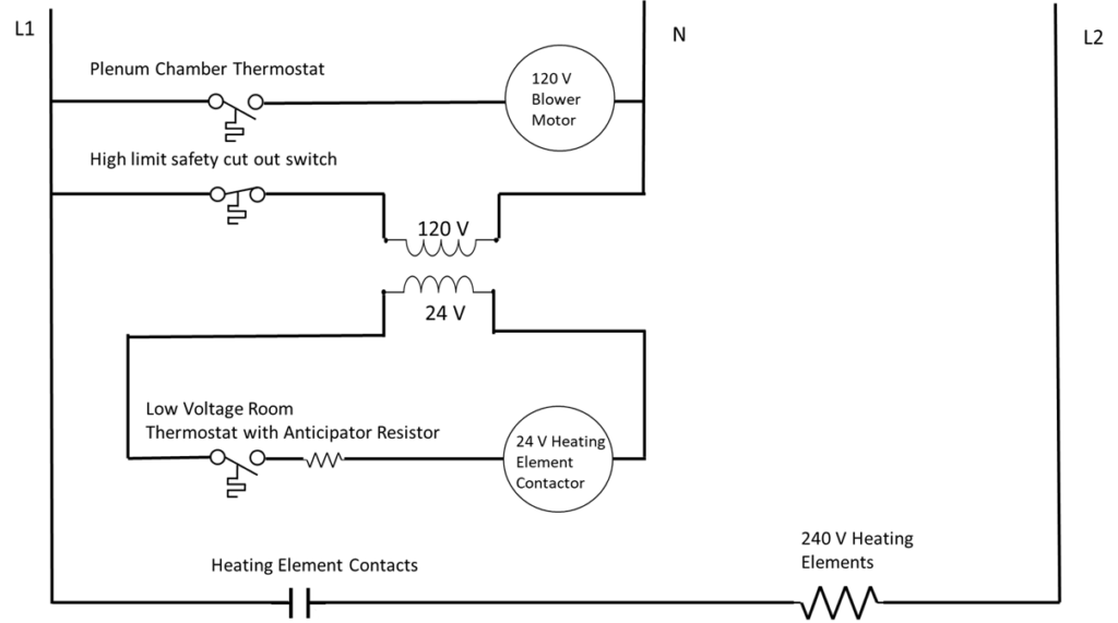
A central electric furnace control circuit
The furnace houses the relays which control the heating elements. These are normally switched on and off in increments of 5 kW or less. This helps reduce the strain on the line due the heavy currents drawn when large heating loads are all switched on simultaneously. This helps reduce the flickering of lights and other under voltage concerns in parallel circuits.
The furnace will also contain a high temperature safety cut-out switch that will disconnect all power to the heating elements if the temperature rises above a pre-set safety threshold. This can happen if the blower fan fails to engage and drive the heated air through the house, and thus draw cool air into the plenum chamber.
Electric furnaces are sized according to their power consumption and can generally range anywhere from 5 kW to 40 kW and be supplied with either single-phase voltage for household use, or three-phase voltage for industrial and commercial heaters, depending upon the availability at the point of installation.
Baseboard Heating
The simplest form of fixed electric heat is the baseboard heater. These small, modular units with their long horizontal profile are installed underneath windows and other areas of high ambient heat loss.
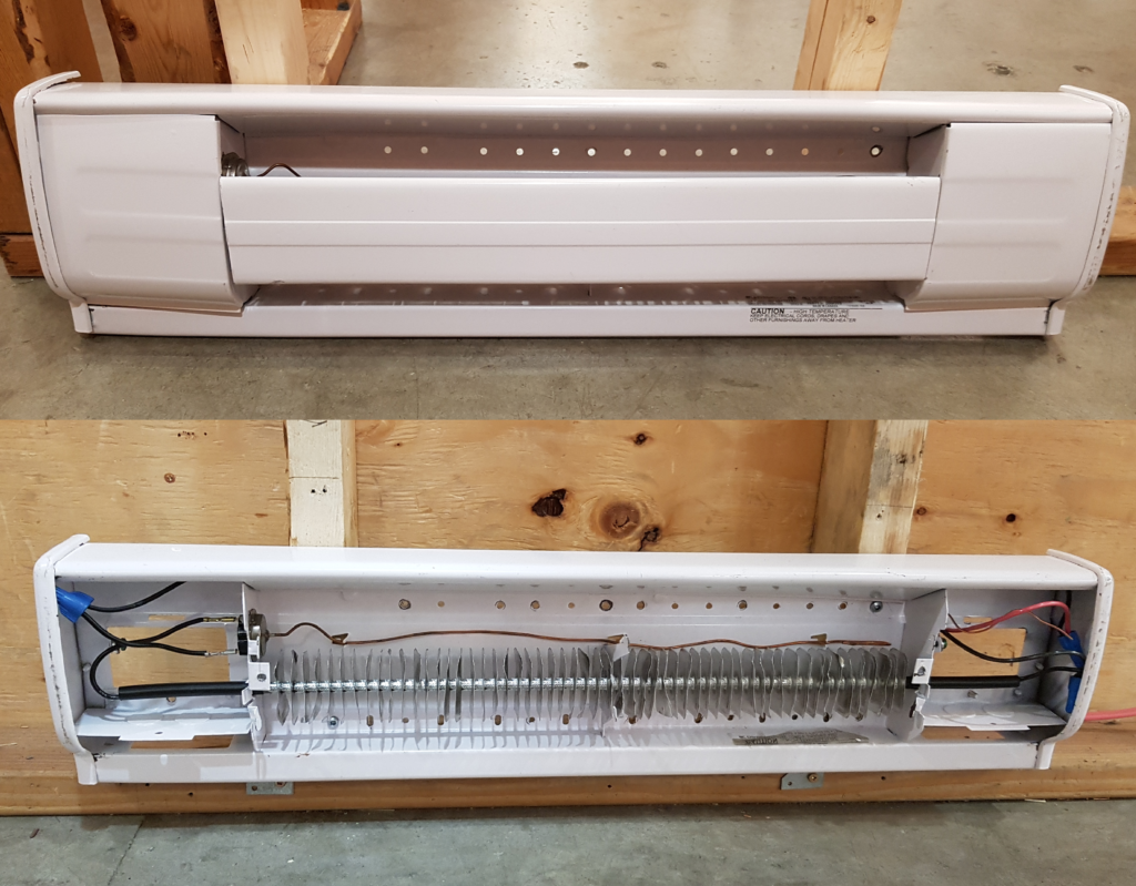
Energized at 240V in households to maximize heat production, baseboard heaters are commonly controlled by line-voltage thermostats installed in each room or heated area though some can also be controlled by built-in thermostats installed directly into the unit housing.
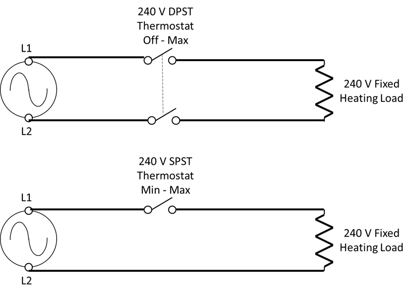
Because line-voltage thermostats directly control the flow of current to the heater element they must be rated for whatever value of current flows through them.
Baseboard heaters are rated for their power output, in watts, and are generally available in 250W increments, thus allowing installers to select the appropriate size of heater for the area being heated. To find the current requirements of a device, divide the rated power by rated voltage.
For example, a thermostat rated 3kW at 240V would be able to handle 12.5 amps of current.
When installing any kind of baseboard heaters, care must be taken not to install any other electrical equipment above them. No receptacles may be installed above a baseboard heater because of the risk of a cord resting on the heater and getting damaged by the heat. If a receptacle is required in a section of wall that also has baseboard heat, some manufactures will provide spacing inside the heater for installation of a receptacle.
Copyright © 2017 PanGlobal. All rights reserved. Under Fair Use Policy.
PanGlobal. (2017). In Heating Systems and Human Comfort. Low Pressure Boiler Components & Operation (2nd ed.). PanGlobal Training Systems Ltd.
Electric Controls: Basic HVAC Copyright © 2021 by Aaron Lee is licensed under a Creative Commons Attribution 4.0 International License, except where otherwise noted.