62 Fuel Systems
Learning Objectives
Outcomes: Describe types of fuel systems and components
Key Question: How is fuel used and delivered in a small engine?
Learning Tasks: read course material
Topics: Safety working around fuel and fuel systems, gravity fed vs fuel pump systems, fuel pumps, carburetors, fuel system common problems and tests
Assessments:online quiz
Estimated time: 1.5 hours
Videos:
Fuel system components: https://www.youtube.com/watch?v=jWW0BsIQ2mQ (4 min)
1. Wear Personal Protective Equipment (PPE): Always wear appropriate PPE such as gloves, safety goggles, and protective clothing to protect against skin contact, eye injuries, and inhalation of fuel vapors.

2. Work in Well-Ventilated Areas: Perform fuel-related tasks in well-ventilated areas to minimize exposure to fuel vapors, which can be harmful if inhaled in high concentrations.
3. Avoid Smoking and Open Flames: Never smoke or use open flames (e.g., welding torches) near fuel storage areas or while working on fuel systems to prevent the risk of fire or explosion.
4. Turn Off Ignition Sources: Ensure that ignition sources such as engines, heaters, and electrical equipment are turned off before working on fuel systems to prevent accidental ignition of fuel vapors.
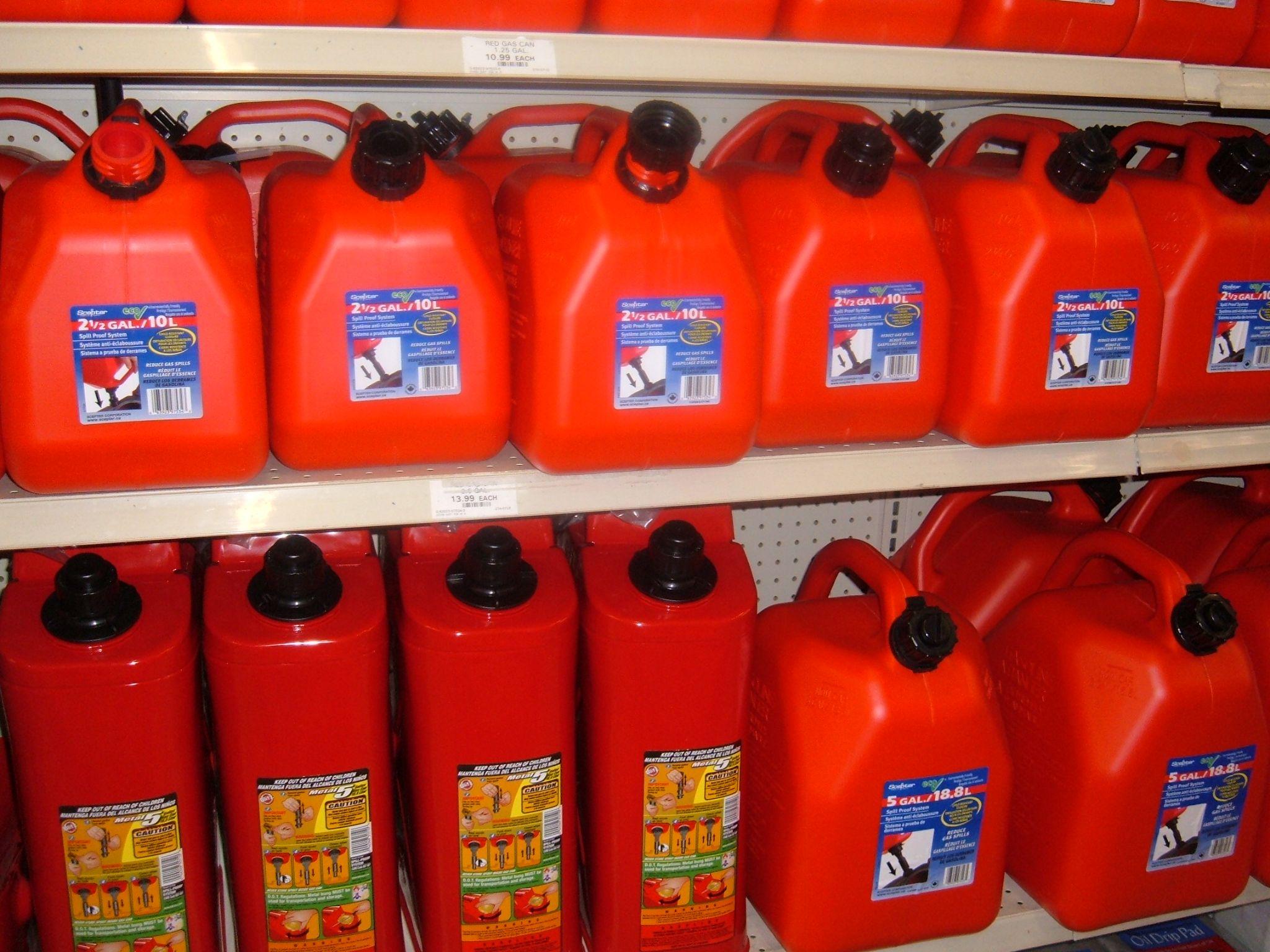
5. Handle Fuel Safely: Use caution when handling fuel and fuel containers to prevent spills and leaks. Store fuel in approved containers and keep them tightly sealed when not in use.
6. Use Proper Fuel Handling Equipment: When transferring fuel, use approved fuel-handling equipment such as funnels, pumps, and hoses to minimize spills and reduce the risk of exposure to fuel.
7. Inspect for Leaks: Regularly inspect fuel lines, fittings, and connections for signs of leaks, such as puddles of fuel or strong fuel odors. Promptly repair any leaks to prevent fuel from coming into contact with hot engine components or electrical systems.
8. Follow Manufacturer Guidelines: Adhere to the manufacturer’s guidelines and specifications for fuel system maintenance, repair, and replacement to ensure the safe and proper operation of the equipment.
9. Dispose of Fuel Properly: Dispose of used fuel and contaminated materials in accordance with local regulations and environmental guidelines to prevent contamination of soil and water sources.
10. Training and Education: Ensure that individuals working with engine fuel and fuel systems receive adequate training and education on safe handling practices, emergency procedures, and hazard recognition.

Gravity Fed Fuel Systems
A gravity-fed fuel system is a simple method of delivering fuel to an engine without the need for a fuel pump. In this system, gravity is used to feed fuel from a fuel tank located above the engine. The force of gravity causes the fuel to flow downward, passing through a fuel line to reach the engine. Gravity fed fuel systems are normally found in smaller engines, such as lawnmowers and chainsaws.
Components of a gravity-fed fuel system typically include:
1. Fuel Tank: The fuel tank is positioned above the engine or at a higher elevation to allow gravity to cause the fuel to flow. It stores the fuel and often has a filler neck for refueling.
2. Fuel Line: A fuel line connects the fuel tank to the engine, providing a pathway for the fuel to travel.
3. Fuel Filter: A fuel filter is often included in the fuel line to remove any contaminants or debris from the fuel before it reaches the engine.
4. Carburetor or Fuel Injector: Depending on the type of engine, a carburetor or fuel injector is used to deliver the fuel to the engine cylinders. The carburetor mixes the fuel with air before it enters the combustion chamber, while a fuel injector sprays fuel directly into the combustion chamber.
In gravity-fed fuel systems, the fuel tank must be located above the engine so that gravity can force the fuel to flow. The fuel then consistently flows through through the fuel line down to the engine. A fuel filter is located along the fuel line to filter out any contaminants before the fuel enters the engine. Once the fuel reaches the engine, it is delivered to the combustion chamber through the carburetor or fuel injector. After this, the fuel is ignited by the spark plug, and combustion takes place.
These systems are simple and reliable. They also require no external power source like electric fuel pumps, making them more energy efficient. Since their effectiveness is dependent on the system being placed above the engine, if the fuel tank is not positioned properly, the system will not work.
Fuel Pump System
The fuel pump system is responsible for delivering fuel from the fuel tank to the engine at the correct air-fuel ratio. This system provides the fuel necessary for combustion to take place within the engine. Unlike gravity-fed fuel systems, fuel pump systems require additional energy either from the electrical system (electric fuel pumps), or mechanical power from the camshaft or crankshaft (mechanical fuel pumps).
The main components of an engine fuel pump system include:
Fuel Pump: Responsible for pumping fuel from the fuel tank to the engine. Fuel pumps can be mechanical- driven by the engine’s camshaft or crankshaft, or electric- powered by the vehicle’s electrical system.
Fuel Filter: Removes contaminants from the fuel, like the ones used in gravity-fed fuel systems. It is located between the fuel pump and the engine.
Fuel Lines: The channel through which fuel travels from the fuel tank to the engine. They are made of metal or reinforced rubber to withstand the high pressure of the fuel system.
Fuel Injectors or Carburetors: Depending on the engine type, fuel is delivered to the combustion chamber through fuel injectors or a carburetor. Fuel injectors spray fuel directly into the combustion chamber, while a carburetor mixes fuel with air before entering the engine.
Fuel Pumps
There are two main types of fuel pumps – mechanical and electrical.
- Mechanical fuel pump systems are more common in older vehicles. They are driven by the engine’s camshaft or crankshaft and use a mechanical motion to pump fuel from the tank to the engine. Mechanical fuel pumps typically consist of a diaphragm, a housing, inlet and outlet valves, and a lever arm.
The pump is mounted on the engine and is directly connected to the camshaft or crankshaft. As the engine rotates, the camshaft or crankshaft drives the lever arm of the fuel pump. The lever arm is connected to a diaphragm inside the pump housing.
Next, a suction stroke takes place. During this stroke, the diaphragm is pulled up by the lever arm, creating a vacuum. This vacuum causes the inlet valve to open, drawing fuel from the fuel tank to the pump.
Then, the diaphragm is pushed down by the lever arm, the inlet valve closes, and the outlet valve opens. This increases the pressure within the pump. The increased pressure forces the fuel out of the pump through the outlet valve, into the fuel lines.
-
Electric fuel pump systems work because of the vehicle’s electrical system. They are more common in modern vehicles and engines. They are more efficient and reliable than mechanical fuel pumps because they provide a consistent pressure and flow rate.
The parts of electric fuel pumps include an electric motor, a pump mechanism, an inlet, and an outlet. Since electric fuel pumps are powered through the electrical system, electricity is supplied to the pump when the ignition is turned on. This starts the pump’s motor.
The motor drives the pump mechanism, drawing fuel from the fuel tank. When fuel is drawn, it is pressurized and then delivered to the engine.
The advantages of the electric fuel pump as opposed to the mechanical fuel pump are consistent fuel delivery and pressure regulation, although they require electrical energy.
Electrical vs mechanical fuel pumps: https://www.youtube.com/watch?v=mhPP6pnisL4 (7 min) or https://www.youtube.com/watch?v=mhPP6pnisL4 (7 min)
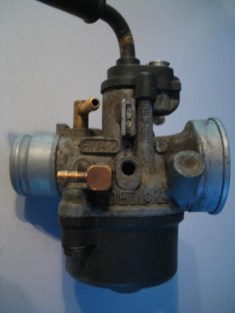
Carburetors
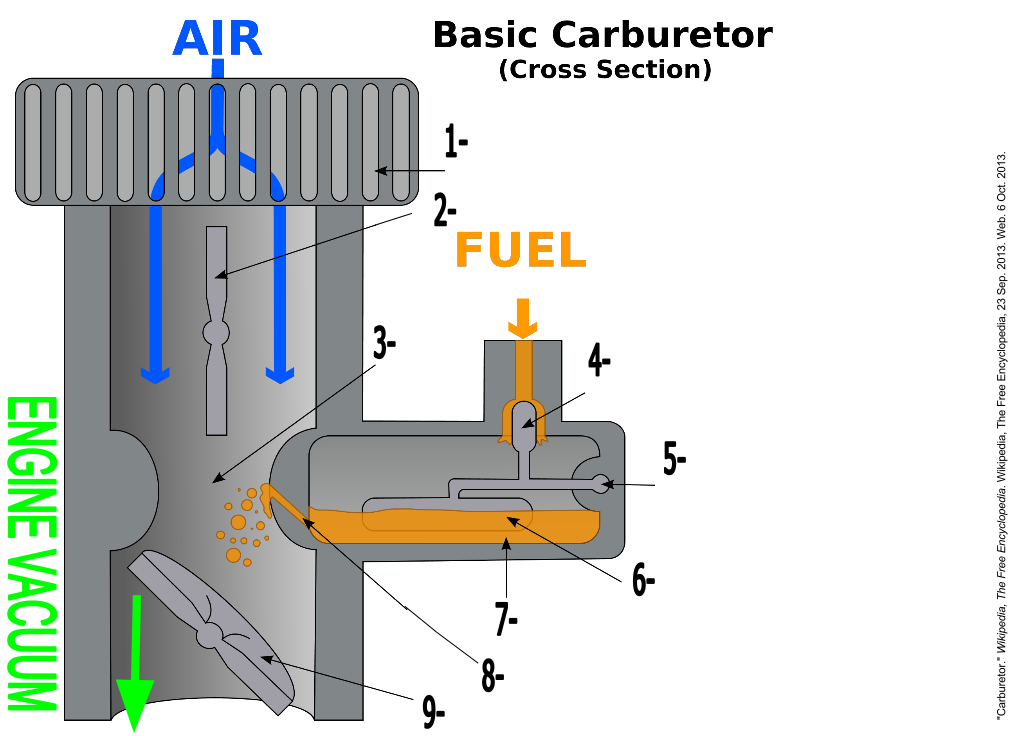
The carburetor’s role is to regulate the amount of petrol introduced into the airflow entering the engine cylinders. As the pistons descend during the induction stroke within the cylinders, the pressure above the cylinders decreases. In naturally aspirated engines (engines with no pressure changers installed), atmospheric pressure facilitates the airflow into the cylinders. Traditionally, carburetors were used to blend petrol with incoming air into the engine. However, basic carburetors can only maintain an accurate air-fuel mixture within a narrow range of engine speeds. For vehicles intended for road use, a broad range of engine speeds and loads is necessary. Complex carburetors are used in these circumstances.
There are three types of carburetors that we will focus on:
Float carburetors: This type of carburetor uses a float to regulate the flow of fuel. When fuel is low in the bowl, the float drops and opens a needle valve, allowing gasoline to enter. The rising fuel level pushes the float up, closing the valve. This action assures a consistent supply of fuel at the carburetor, regardless of fluctuations in fuel pump performance or gravity feed.
Float carburetor: https://www.youtube.com/watch?v=DbNFJYbzUoM (2 min)
Diaphragm carburetors: This kind of carburetor is used on equipment that must operate in many positions, such as a chain saw. It contains one or more pulsating diaphragms, which act as pumps to supply fuel to the carburetor jets. Unlike floats, diaphragms are not affected by gravity.
Suction lift carburetors: The simple suction lift carburetor is mounted on top of the gas tank. Air rushing through the air horn forms a partial vacuum that draws fuel up a pipe to the carburetor jet, where it is atomized. The principle is identical to the one used in perfume atomizers. The carburetor has one or two fuel pipes. Those with two have a simple diaphragm fuel pump at the top of the longer pipe. Some of these diaphragms have flaps that act as one-way valves to control fuel flow. Others use fiber discs or balls for the same purpose.
Fuel Pump System Common Problems and Tests
Here are some of the most common problems and tests associated with fuel pump systems:
Fuel Pump Failure: Over time, the fuel pump may wear out or fail due to factors such as age, high mileage, or contamination. Symptoms of fuel pump failure include engine sputtering, loss of power, and difficulty starting.
Fuel Pump Noise: A buzzing or whining noise coming from the fuel tank area may indicate a failing fuel pump or a clogged fuel filter.
Fuel Leaks: Leaks in the fuel lines, fittings, or fuel pump housing can result in fuel leakage, posing a fire hazard and leading to fuel system inefficiency.
Low Fuel Pressure: Insufficient fuel pressure can cause engine stalling and poor acceleration. Low fuel pressure may be caused by a weak fuel pump, clogged fuel filter, or faulty fuel pressure regulator.
Fuel Contamination: Contaminants such as dirt, rust, or water in the fuel system can clog fuel filters, injectors, and the fuel pump, leading to engine performance issues and potential damage.
Tests:
Fuel Pressure Test: Use a fuel pressure gauge to measure the fuel pressure. Compare the measured pressure to the manufacturer’s specifications to determine if the fuel pump is operating within the acceptable range.
Fuel Volume Test: Perform a fuel volume test to measure the amount of fuel delivered by the fuel pump over a specified period. Insufficient fuel volume may indicate a weak or failing fuel pump.
Fuel Pump Noise Test: Listen for abnormal noises, such as buzzing or whining coming from the fuel tank area while the engine is running.
Fuel Pressure Leak Down Test: Perform a fuel pressure leak-down test to check for fuel pressure loss over time after the engine is turned off. A significant pressure drop may indicate a leaking fuel injector, fuel pressure regulator, or check valve.
Visual Inspection: Inspect the fuel pump, fuel lines, and connections for signs of leaks, damage, or corrosion. Check for fuel odours and wet spots around the fuel pump assembly and fuel lines.
Videos:
Small engine fuel pump tests: https://www.youtube.com/watch?v=4MDtc9VF0dQ (4 min)
Fuel Diagnostics: https://www.youtube.com/watch?v=0PrgUOAG-fU (9 min)
References
Fuel tests:
1. Dempsey, Tony. “101 Projects for Your Porsche 911.” Motorbooks, 2001.
2. Haynes, John Harold. “Automotive Fuel and Emissions Control Systems.” Haynes Manuals N. America, Incorporated, 2000.
3. Watson, Larry. “Fuel Pump Testing.” Hot Rod Network, 2016.
Fuel Pump Systems:
1. Heywood, John B. “Internal Combustion Engine Fundamentals.” McGraw-Hill Education, 1988.
2. Stone, Richard. “Introduction to Internal Combustion Engines.” Macmillan International Higher Education, 1999.
3. Pulkrabek, Willard W. “Engineering Fundamentals of the Internal Combustion Engine.” Pearson, 2003.
4. Dixon, John. “The Complete Guide to Small Engine Repair.” Cool Springs Press, 2009.
5. Demorro, Kevin. “Small Engine Repair: 5.5 HP Through 20 HP Four Stroke Engines.” Independently Published, 2019.
6. Clarke, Tim. “How to Repair Briggs and Stratton Engines.” CreateSpace Independent Publishing Platform, 2010.
Gravity fed fuel systems:
1. National Highway Traffic Safety Administration (NHTSA). “Gravity Fed Fuel System.” Safercar.gov, www.safercar.gov/Vehicle-Shoppers/Air-Bags/Gravity-Fed-Fuel-System. Accessed 6 Mar. 2024.
2. Kershaw, Vic. “Fuel Systems for IC Engines.” Institution of Mechanical Engineers, 1999.
Safety:
1. Occupational Safety and Health Administration (OSHA). “Hazard Alert – Portable Gas Cans.” U.S. Department of Labor, www.osha.gov/Publications/OSHA3696.pdf.
2. National Fire Protection Association (NFPA). “NFPA 30: Flammable and Combustible Liquids Code.” www.nfpa.org/codes-and-standards/all-codes-and-standards/list-of-codes-and-standards/detail?code=30.
3. Canadian Centre for Occupational Health and Safety (CCOHS). “Gasoline Handling.” www.ccohs.ca/oshanswers/chemicals/gasoline/intro.html