56 Fuel and Combustion
Learning Objectives
- Explain natural and mechanical draft
- Describe the use, advantages, and characteristics of common boiler fuels
- State the requirements and reactions for complete and incomplete combustion
- Describe the operation of atmospheric and ring gas burners
Essential Question
How is heat generated in the boiler?
Introduction
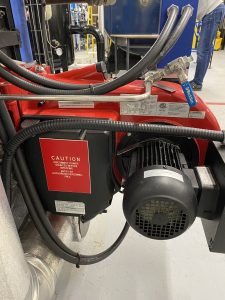
| Forced Draft (FD) | In most packaged firetube boilers, a motor-driven fan is positioned in front of the boiler to force combustion air into the furnace. This creates positive pressure within the furnace and flue gas passes, necessitating a gas-tight boiler structure, including sealed openings like observation ports. The fan typically utilizes a centrifugal design, featuring an impeller mounted on a shaft within a volute-shaped housing. Atmospheric air is drawn in through the inlet ring and accelerated by the rotating impeller’s vanes, exiting the impeller rim at high velocity. As the air travels through the housing to the outlet, its velocity gradually decreases, converting kinetic energy into the pressure energy needed to propel the air into the furnace.
Compared to an induced draft (ID) fan, the forced draft (FD) fan is more cost-effective as it only handles cool air and doesn’t manage fuel fed to the burner. Additionally, it operates at lower temperatures, allowing for the use of less expensive materials. Moreover, it handles a smaller volume of air than an ID fan. |
| Induced Draft (ID) | In this approach, the combustion air required is induced into the furnace by creating a negative pressure within the furnace relative to atmospheric pressure, achieved through an induced draft fan positioned between the boiler’s flue gas outlet and the chimney. The fan draws the combustion gases from the furnace, maintaining a sub-atmospheric pressure inside, and channels these gases to the chimney. While induced draft is less frequently utilized compared to forced draft in heating boilers, both methods necessitate the use of a chimney. Although the chimney isn’t essential for generating draft, it’s essential for expelling combustion gases to the atmosphere at an appropriate height for pollution dispersion.
In the past, on older boilers where stack height options were limited, induced draft was often created using a “venturi” in the uptake area, sometimes powered by steam. This principle was commonly employed in many locomotive boilers. |
| Balanced Draft (BD) | Larger boilers often utilize both forced draft (FD) and induced draft (ID) methods simultaneously. This dual approach enables more precise regulation of furnace pressure, typically maintained slightly below atmospheric pressure. When furnace pressure can be consistently upheld at a fixed level irrespective of the firing rate, it’s referred to as balanced draft. |
Draft Control
The fan or blower responsible for supplying combustion air or handling flue gases typically operates using a constant-speed electric motor. Its capacity is designed to meet the maximum air requirements of the boiler under full load conditions. In instances where the boiler is equipped with a modulating control system and motor to adjust fuel supply for maintaining consistent steam pressure or water temperature at varying loads, air supply must be similarly regulated in direct correlation with fuel input.
Various methods are employed for this purpose:
- Inlet Damper Control: A damper installed in the inlet duct to the fan adjusts the volume of air drawn into the fan.
- Outlet Damper Control: Placed at the fan’s outlet, this damper controls the volume of air directed towards the burner.
- Rotary Damper Control: Damper vanes encircle the burner, regulating airflow to it.
However, these control mechanisms introduce restrictions to air and/or gas flow, leading to increased velocity or kinetic energy. This heightened kinetic energy results in lower potential energy, as pressure is a form of potential energy. Consequently, this leads to a negative pressure environment within the furnace, presenting a challenge in draft control.
Fuels
Use, Advantages, and Characteristics
Fuels can be classified into three groups:
- Solid fuel – coal, wood, etc.
- Liquid fuel – fuel oils, gasoline, etc.
- Gaseous fuel – natural gas, propane, butane, etc.
Coal
Coal is comprised of several elements including carbon, hydrogen, oxygen, sulphur, nitrogen, moisture, and ash. However, only carbon, hydrogen, and sulphur are combustible components of coal. Hydrogen, when combined with some carbon, forms hydrocarbons, referred to as volatile material, which vaporize as gas when the coal is heated. The remaining carbon, not combined with hydrogen, is termed fixed carbon. Sulphur, although combustible, constitutes a small percentage of coal’s composition and is considered an impurity due to its combustion byproduct, sulphur dioxide, which can cause corrosion in boilers and chimneys and contribute to air pollution. Since coal is not typically utilized as a fuel in buildings, it will not be discussed further in this chapter.
Fuel Oil
Fuel oils are petroleum-derived products originating from crude oil, a mixture of various hydrocarbon compounds ranging from light gases to heavy semi-solid substances. Refineries utilize fractional distillation to separate crude oil into distinct groups based on characteristics such as boiling point, specific gravity, and viscosity. These groups encompass gases and liquids like methane, gasoline, jet fuel, kerosene, diesel fuel, light fuel oils, lubricating oils, heavy oils, and residue.
The boundaries between these groups are often blurry, leading to overlaps; for instance, diesel fuel and light fuel oil ranges may intersect. Consequently, some diesel fuels closely resemble light fuel oils, with No. 2 diesel fuel closely resembling No. 2 fuel oil, the prevalent oil type for packaged firetube boilers. Fuel oils consist mainly of carbon and hydrogen in the form of hydrocarbons, with minor amounts of oxygen, sulphur, nitrogen, and trace ash.
Fuel oils are categorized by grade numbers based on characteristics such as relative density (specific gravity), indicating whether they are lighter or heavier than water; viscosity, which measures internal resistance to flow and is expressed in Saybolt Seconds Universal (SSU); and flash point, denoting the lowest temperature at which the oil emits enough vapor to ignite but does not sustain combustion.
The fire point is the temperature at which a fuel continues to burn once ignited, exceeding the flash point temperature. Typically, the fire point is approximately 25°C (50°F) higher than the flash point, providing a guideline: Flash Point + 25°C (+50°F) = Fire Point.
The flash point temperature serves as a reliable indicator of the fire hazard associated with storing and pumping oil. Because fuel oils generally have flash points well above ambient temperatures, they are considered relatively safe fuels for storage, even indoors.
The following table classifies fuel oil, their application, and some characteristics. The table is taken directly from PanGlobal (2017) under the Fair Use Policy.
| Commercial Grade No. | Relative Density at 15.0°C (60°F) | Viscosity SSU at 38°C (100°F) | Minimum Flash Point °C (°F) | Application |
| 1 | 0.815 | 31 | 37.8 (100) | Light Domestic |
| 2 | 0.86 | 32-39 | 37.8 (100) | Medium Domestic |
| 3 | 0.92 | 45-120 | 54 (130) | Light Industrial |
| 4 | 0.95 | 140-700 | 54 (130) | Medium Industrial |
| 5 | 0.98 | 900+ | 66 (150) | Heavy Industrial |
Grades 1 and 2, often referred to as furnace oils, exhibit relatively low viscosity and density. They don’t necessitate preheating before being utilized in boiler furnaces. Grade 2 oil stands out as the most commonly used fuel oil for residential, small commercial, or industrial heating systems.
On the other hand, Grades 4 and 5 are heavier oils with higher viscosities. They demand heating during storage and pumping, and additional heating, usually up to around 95°C (203°F), before they are suitably combusted in a furnace.
Fuel oils offer several advantages over coal as a boiler fuel:
- They require less storage space.
- Their feed to the furnace can be more precisely controlled.
- They entail less handling equipment and labor.
- They tend to burn more cleanly with fewer residuals, ensuring efficient utilization.
However, a big disadvantage is that oil is pricier and less readily available compared to coal.
Natural Gas
Natural gas is procured from gas wells drilled in gas-rich rock formations or as a by-product from oil wells. Typically, processing is necessary to eliminate any undesirable components before it is transported to the market. The primary components of natural gas supplied to consumers include the hydrocarbons methane (80%-90%) and ethane (10%-20%). Additionally, it may contain traces of propane, butane, nitrogen, oxygen, carbon dioxide, and hydrogen sulphide.
The advantages of natural gas as a boiler fuel are as follows:
- It generates no ash when burned.
- Minimal handling equipment is needed.
- The quantity fed to the furnace can be easily regulated.
- It readily mixes with air.
- It is exceptionally clean, leaving no spills, mess, or residue.
- There is no need for storage space.
Natural gas, on the other hand, tends to be pricier than coal and, in certain areas, oil. Its transmission from the source to the heating plant necessitates lengthy pipelines. The comparative economics concerning the cost and availability of natural gas versus oil hinge on various factors and are unique to each location.
Liquified Petroleum Gases
Fuel Heating Value
When fuel undergoes complete combustion, the resulting heat generated is referred to as the heating value of the fuel. This unit amount can be specified as a mass unit (such as kilogram or pound) or a volume unit (like cubic meter or cubic foot), depending on the fuel type.
The heating value of a fuel is primarily determined by the quantity of carbon, hydrogen, and sulfur present in the fuel composition.
Below are typical average heating values for various fuels:
| Fuel | Heating Value (SO) | Heating Value (USCS) |
| Coal (bituminous) | 25 600 kJ/kg | 11 000 Btu/lb |
| Fuel Oil (light) | 45 360 kJ/kg | 19 500 Btu/lb |
| Natural Gas | 37 260 kJ/m3 | 1 000 Btu/ft3 |
| Propane | 93 150 kJ/m3 | 2 500 Btu/ft3 |
| Butane | 122 200 kJ/m3 | 3 280 Btu/ft3 |
Complete and Incomplete Combustion
Theory of Combustion
During combustion, the primary combustible elements of the fuel, including carbon, hydrogen, and sulfur, chemically combine with oxygen from the air, resulting in the generation of heat. Combustion is essentially the rapid oxidation of fuel, leading to the production of significant amounts of heat.
To achieve complete combustion of the fuel within the furnace, several conditions must be met:
- Sufficient air must be supplied to the furnace to provide ample oxygen for the combustion of all combustible elements of the fuel.
- Proper mixing of air and fuel is essential to ensure that each fuel particle comes into contact with the necessary oxygen. This thorough mixing is referred to as turbulence.
- The temperature within the furnace needs to be sufficiently high to ignite the fuel as it enters.
- The furnace must be adequately sized to allow enough time for combustion to occur fully before the gases come into contact with cooler surfaces.
These conditions are often summarized as the combination of enough air plus enough time, temperature, and turbulence, collectively known as the three T’s of combustion. If any of these conditions are not met, incomplete or poor combustion may occur.
It’s crucial to distinguish between “proper” and “complete” combustion. In “proper” combustion, the smallest particles of fuel and oxygen unite simultaneously, ensuring that no carbon monoxide (CO) is formed, and complete combustion occurs. However, in “complete” combustion, carbon may initially form CO before further oxidizing to carbon dioxide (CO 2). While this still results in complete combustion, it may not be considered proper because CO is an undesired byproduct.
To ensure both complete and proper combustion, it’s essential to facilitate good contact between oxygen and the fuel. This can be achieved by designing the burner to promote thorough mixing of fuel and combustion air and by supplying excess oxygen to the burner through the provision of excess air.
| Complete Combustion | Of the combustible elements present in a fuel, carbon typically constitutes the largest percentage. In an ideal scenario of complete and proper combustion as described previously:
It’s important to emphasize that in these processes, there are no residual oxygen atoms remaining in the resulting flue gases. This condition is referred to as “Theoretical Combustion,” although it’s not entirely achievable in practical applications. Non-combustible elements present in the fuel will not undergo oxidation but may either form ash or pass through the furnace without change. |
All About Complete Combustion | Heating Theory Course | SkillCat (youtube.com) |
| Incomplete Combustion | If any of the conditions necessary for complete combustion are not met, the combustible elements won’t fully react with oxygen:
The presence of unburned fuel exiting the furnace in these instances might appear puzzling, but it can be understood through the concept of “balancing a chemical equation.” |
Hotels | Introductions | Big Sampson | DC YT | CAEN | 16×9 | 30 (youtube.com) |
Combustion Air and Excess Air
Air primarily consists of a blend of oxygen and nitrogen, with approximate proportions of 21% oxygen and 79% nitrogen by volume.
For complete combustion, the necessary oxygen is sourced from the air supplied to the furnace. The quantity of air needed to provide precisely enough oxygen for complete combustion is termed theoretical air. However, in practical applications, it’s essential to supply more air than this theoretical amount to ensure that all fuel particles come into contact with oxygen. The surplus air beyond the theoretical requirement is referred to as excess air, typically expressed as a percentage of the theoretical air.
Minimizing the amount of excess air supplied to the furnace is preferred due to the high temperature at which the air is heated in the furnace, resulting in a substantial amount of heat being carried away through the stack. Additionally, reducing excess air can lead to a decrease in the power required for a forced draft fan.
However, excessive reduction of excess air can lead to incomplete combustion, which may result in the formation of carbon monoxide and free hydrogen, as previously discussed. Therefore, a balance must be struck to ensure optimal combustion efficiency without compromising safety.
Burners
The primary role of a burner is to facilitate the thorough mixing of fuel and air, ensuring optimal oxygen-to-fuel contact. Essentially, the burner serves as the central component of a boiler, playing a crucial role in its operation and overall efficiency. A well-functioning burner maximizes combustion efficiency, resulting in greater fuel efficiency and minimal pollutant emissions. Conversely, if a burner operates improperly, it can lead to serious consequences.
Burners are utilized across a wide range of applications, from small camp stoves to large-scale gas-fired heating systems and power boilers. There are notable distinctions between various types and designs of burners, with differences particularly evident between those used for gas furnaces and fuel oil systems. Boiler operators are expected to possess familiarity with the diverse types of burners and their associated components, though this chapter will focus solely on those used for liquid and gaseous fuels, excluding those designed for solid fuels.
Combustion Air
Gas Burners
Gas burners are broadly categorized into two main types:
- Atmospheric Burners: These units operate without the need for a fan and are commonly found in residential applications such as hot water heaters, camping stoves, and gas-fired kitchen ranges.
- Power Burners: This type of burner incorporates a forced draft (FD) fan to supply the combustion air. Power burners are prevalent in larger heating and power boilers.
Gas burners can further be classified based on how air and fuel are mixed:
- Premix Burner: In a premix burner, combustion air is mixed with the gas inside the burner before the gas exits the burner head. This ensures thorough mixing of the air and fuel before combustion.
- After-mix Burner: In contrast, an after-mix burner mixes the combustion air with the gas after it leaves the burner. This occurs outside the burner head.
| Atmospheric Burners | The operation of a premix atmospheric burner, widely used in various appliances, involves the following steps:
In smaller burners, the gas flow through the orifice or nozzle is typically not adjustable, as it depends on the size of the orifice or nozzle and the gas supply pressure. However, in larger burners, the gas flow can be adjusted using a small needle valve. Additionally, the amount of primary air can be adjusted by enlarging the air opening in the mixing head through the use of a disc or plate. Premix Percentage: Burner Heads: A diverse range of burner heads is available, each designed for specific applications. Common designs include circular heads for ranges, circular with ribbon-type porting for camp stoves, rectangular with ribbon-type porting for residential furnaces, and rectangular with round ports for small heating boilers. The choice of type and size depends on the intended use and operational requirements. |
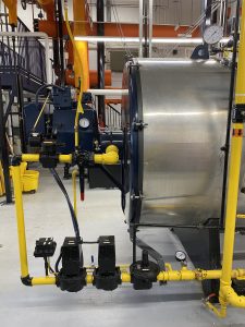
| Ring Burners | The ring burner is a type of burner commonly employed in packaged boilers (as shown in Fig. 5). It comprises a ring-shaped, hollow casting installed in the firing aperture of the furnace. Small apertures are drilled into the face of this ring, facilitating the direction of gas into the air stream at or close to right angles, which aids in gas shearing. Additionally, deflector vanes are incorporated to impart a spreading or swirling motion to the air before its entry into the furnace, facilitating thorough mixing with the gas.
This burner design is categorized as an after-mix or outside mixing type, as the gas and air blend together after exiting the burner. |
Combination Burners
The utilization of natural gas as a boiler fuel presents several advantages, notably the elimination of storage space requirements, as the gas is directly supplied through the gas company’s distribution line. Nonetheless, this convenience can pose a disadvantage, as any interruption in the gas supply will promptly shut down the plant operations.
To mitigate this risk, many heating plants incorporate provisions for standby fuel availability to use during natural gas supply interruptions. Common standby fuels include liquefied petroleum (LP) gas or fuel oil.
Numerous gas burners are engineered to accommodate both natural gas and LP gas or liquid fuels. However, this necessitates separate controls for each fuel supply line to the shared burner, given the significant variations in the heating values of these fuels. When oil serves as a standby fuel for a gas-fired boiler, a separate oil burner becomes necessary.
Example: In a combined gas and oil-fired burner setup, the boiler is equipped with a ring-type burner for gas firing and a gun-type burner for oil firing, ensuring versatility and reliability in fuel usage.
Copyright © 2017 PanGlobal. All rights reserved. Under Fair Use Policy.
PanGlobal. (2017). In Fuel and Combustion. Low Pressure Boiler Components & Operation (2nd ed.). PanGlobal Training Systems Ltd.