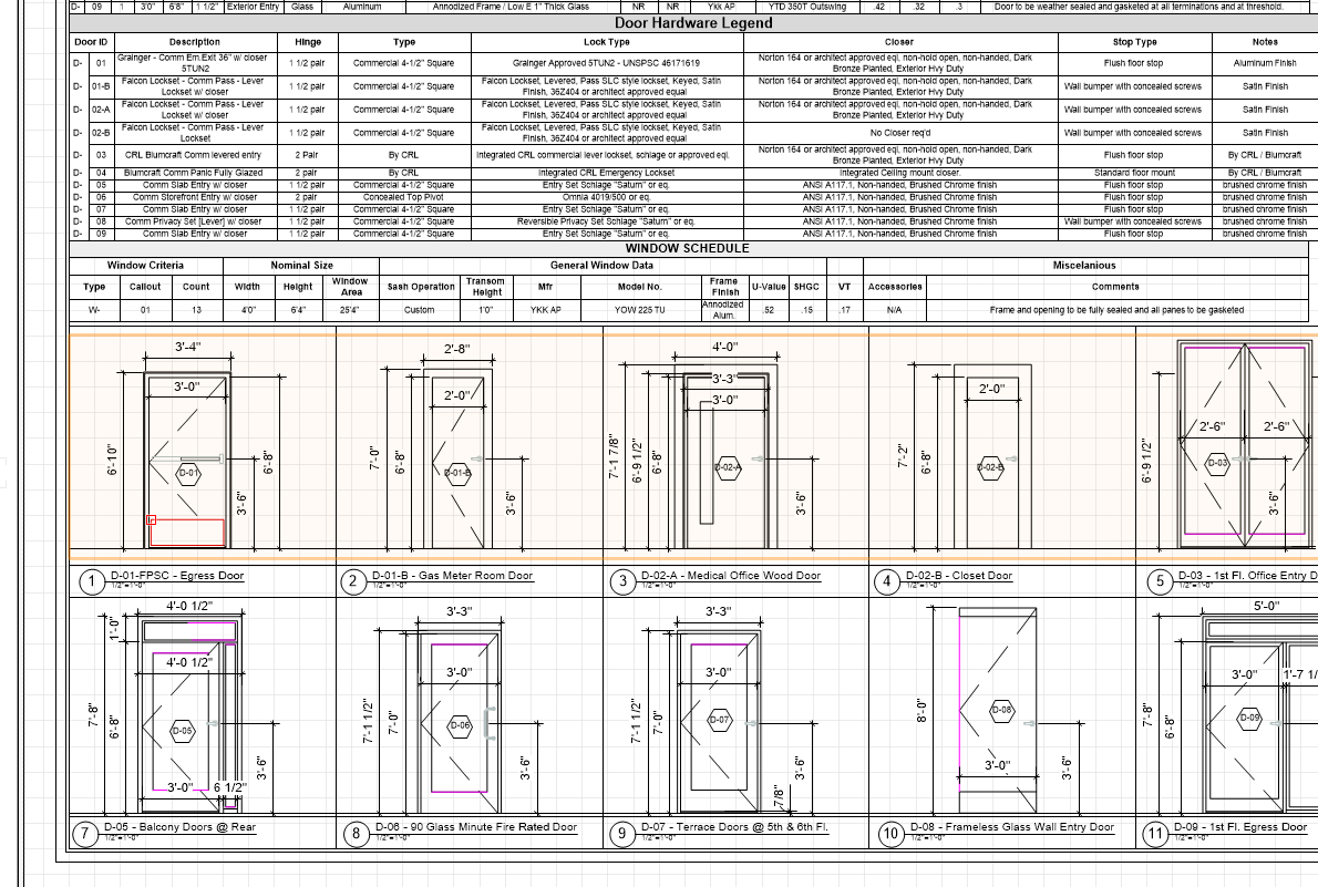
47 Framing
Learning Objectives
Use materials and tools to construct framing.
This unit will introduce platform or western framing, the most common method of framing residential and small commercial buildings.
Platform Framing
Floor Framing
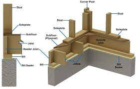
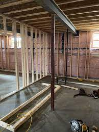
A floor frame consists of members fastened together to support the loads a floor is expected to bear. The floor frame sits on a foundation – concrete or PWF. The floor frame is anchored to the foundation and is the level floor that all the rest of the construction is built upon.
In the usual order of installation, the floor frame consists of, sill plates, posts or columns, beams, joists, bridging, and sub-flooring.
- Anchor Bolts specially designed steel bolts cast into the concrete foundation used to bolt the sill plates to the foundation.
- Sill Plates Lumber – 2 x 4 or larger, bolted to the concrete foundation with anchor bolts.
- Posts or Columns Vertical framing members of wood or steel that support (and are anchored to) beams or lintels, supported by piers, or pads.
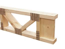
- Beams or Lintels Horizontal framing members of wood, steel or concrete supporting joists in a floor system. They are supported by (and are anchored to) the foundation and by posts or columns or bearing walls .Wood Beams can be solid, built up, or engineered.
- Joists Usually wood or engineered wood horizontal framing members that rest on the sill plates and beams. These members support (and are anchored to) the sub-floor.
- Bridging Any type of framing member that restrains joists from twisting or deflecting. Bridging also stiffens floor systems.
- Sub-Floor The sub-floor is sheet stock – plywood or OSB or solid wood that is attached to the joists. It is the support for the finish floor. The sub-floor adds significant strength to the floor system.
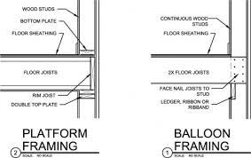
The Box Sill Method
As shown in the diagram, the sills – commonly 2 x 4 or 2 x 6 lumber – are bolted to the concrete foundation using the anchor bolts that were cast into the concrete. A sill gasket or caulking between the sill and the foundation help make this joint weather tight. The floor joists are attached to the sill and to a beam or beams. Rim joists are attached to the sill and the ends of the joists. This is the most common method used in residential construction.
The Joist Embedded Method
Beams, joist and headers and subfloor are positioned before the concrete is poured. The joists are partially embedded in the concrete walls. This method was popular in the days when concrete was wheel-barrowed to the forms – concrete could be delivered to the barrows on the subfloor, and dumped into the forms. Not so common now that concrete pumps are available.
Types of Beams
The National Building Code of Canada (NBC) gives the minimal sizes and maximum spans (tables A-8, A-9, pages 336, 337). Canadian Wood-Frame House Construction (tables 20 & 21, pages 200- 203).
Built up and engineered beams are the common choice for residential construction. Beam sizes and descriptions are generally listed on the plans.
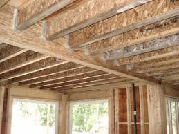
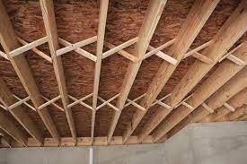
Floor Joists or Trusses
Floor joists or trusses are the horizontal members of a floor system. Laid out on centers, (mostly 16 inch centers), they rest on and transfer the load to sills and beams. In residential construction, nominal 2-inch (actual 1 1/2″) thick lumber placed on edge has been traditionally used. These joists will require a beam at mid span in the average house construction.
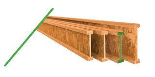
Truss joists and engineered I joists have become increasingly popular for several reasons. Because they are not subject to the shrinkage and warping of solid wood, Truss and I beam joists will not squeak. They will also span greater distances and will allow the placement of air ducts and other mechanicals inside the joist leaving the living space below free of beams and boxed ducts.
The floor system’s structural requirements are noted on the plans and can be computed using the tables found in The National Building Code of Canada.
Bridging
The NBC states that the bottoms of floor joists must be restrained from twisting (9.23.9.3, pages 274, 275).
Bridging is used to restrain and stiffen floor joists. The simplest bridging is a 1 x 4 nailed on centers to the bottom of the joists, and attached to the rim joists. Bridging can also be set between the joists, either cross bridging, or solid lumber. The National Building Code of Canada contains the requirements for bridging.
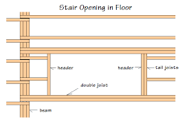
Framing Floor Openings
The National Building Code of Canada (NBC) gives the minimal sizes of openings that must have header and trimmers installed, nail spacing and materials. (9.23.9.5)
Installing Rim of Header Joists
After the rim joists are laid out, place them in position and toenail them to the sill. Then position all full length joists in position.
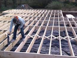
Installing Floor Joists
Stack the necessary number of full-length floor joists at intervals along both walls. Each joist is carefully sighted along its length by eye. Any joist with a severe crook or other warp should not be used. The crown of any joists must be placed up.
Joists are to be doubled where extra loads must be supported. The National Building Code of Canada (NBC) gives the minimal sizes (9.23.9.8., page 275). Place these joists in their location next. Repeat the operation for the opposite wall.
Joist Framing at the Sill
Joists should rest on at least 11/2 inch of bearing on wood and 3 inches on masonry. The National Building Code of Canada (NBC) gives the minimal end bearing (9.23.9.1., page 274). In platform construction, the ends of floor joists are capped with a header joist, also called a rim joist. In a balloon frame, joists are cut flush with the outside edge of the sill. The use of wood
I-beams requires sill construction as recommended by the manufacturer for satisfactory performance of the frame.
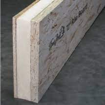
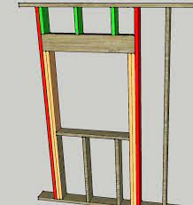
One of the challenges with wood I-beams (engineered) joists is what to do at the end of joist. It is difficult to insulate and seal properly around the perimeter of the floor.
A recent solution is the EMERCOR Insulated Rimboard (E-RIM) which provides both excellent insulation (R-14) and protection from moisture. The E-RIM is made up of two exterior layers of OSB board with a rigid polyurethane foam core (see graphic below). It is attached right at the end of the I-beam joist flush with the edge of the sill. It can support both lateral and vertical loads. It also provides a solid surface for nailing siding, other sheathing or deck ledgers, etc. For details, see the manufacturer’s brochure provided as a handout.
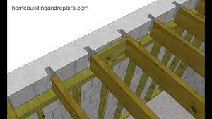
Joist Framing at the Beams
If joists are lapped over the beams, the minimum amount of the lap is 6 inches and the maximum overhang is 12 inches. There is no need to lap wood I-beams. They come in lengths long enough to span the building. However, they may need to be supported by beams depending on the span and size of the I-beam.
Headroom may be gained by framing floor joists into the side of the beams using joist hangers.
Notching and Boring of Joists
Notches should not be located in the middle 1/3 of the joist span. Notches on the ends should not exceed 1/6 of the joist depth.
Notches in the top of sawn lumber floor joists should not exceed 1/6 of the joist depth. Holes bored in joists for piping or wiring should not be larger than 1/3 of the joist depth. They should not be closer than 2 inches to the top or bottom of the joist.
Some wood I-beams are manufactured with 1/2 inch perforated knockouts in the web at approximately 12 inches on centers along its length. This allows easy installation of wiring and pipes. To cut other size holes in the web, consult the manufacturer’s specifications guide. Do not cut or notch the flanges of wood I-beams.
Subfloors
The National Building Code (NBC) states that subflooring shall be provided beneath the finished flooring (9.23.14, page 283). Subfloor may consist of plywood, shiplap, oriented strand board, or lumber. The National Building Code gives the sizes in table (9.23.14.a, page 283).
Laying a Sheet Stock Sub Floor
Plywood and OSB provide a smooth, solid, stable base for any kind of finish flooring. Sheets require blocking around the edges if the sheets are not tongue and groove. The correct thickness, applications and the nailing requirements can be found in the National Building Code of Canada.
Snap a chalk line the width of the sheet stock from the edge of the building, at right angles to the joists. Line up the sheets to this line. This will ensure the row of plywood/OSB will run straight. Blocking will be required if the sheets are not tongue and groove.
Begin the second row of sheets at the end of the building, alongside the first sheet laid. Cut a sheet in half (4 x 4), and start on the other side of the chalk line. Continue to lay and nail sheets in this row. The next (third) row of sheets is started with a full sheet. This will stagger the joints and provide the strongest floor.
It is now common practice to use subfloor adhesive and deck screws to attach subfloors to floor joists. This practice greatly reduces floor squeaks and provides a much stronger floor structure.
Wall Framing
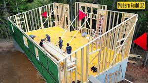
The term platform framing refers to the construction of a platform or floor, the erecton of walls and partitions (interior walls) and the construction of a roof or another platform on top of the walls if the building is two story.
Walls are commonly framed and sheathed (or braced if no sheathing is used) lying flat on the platform, then erected. With small buildings, it is common to frame all 4 exterior walls and then stand them up.
Terminology
Bearing Wall A wall that carries a load from the structure above; opposite of a non bearing wall.
Blocking Any piece of lumber let into a wall for the purpose of attaching partitions or hardware to the wall.
Bracing Walls require bracing or sheathing to stiffen and strengthen them.
Cripple Vertical framing member situated between the plate and the lintel, or the bottom plate and the rough sill.
Lintel A horizontal framing member that spans an opening, aka a beam or header. Commonly built up of two or more pieces of 2” nominal lumber.
Partition An interior wall.
Plate Horizontal members of a wall frame, nailed to the vertical members: studs, cripples, and trimmers. One bottom plate, and two top plates. The top plate overlaps the walls and partitions and locks the top of the walls together.
Rough Sill The bottom horizontal member of an opening.
Sheathing Sheet stock (plywood or OSB) or lumber used to cover and make rigid wall systems. Lumber sheathing requires bracing.
Stud Vertical members of a wall frame when sheathed or braced will transfer the load from above (floors, ceilings, roof structures and live loads) to the floor system and foundation.
Trimmer A vertical framing member holding up both ends of a lintel.
Procedures for Framing
A three person crew would commonly frame the walls of a building in the following way: The Journeyman or Lead Hand would take the prints and start laying out the plates for the exterior walls, and the Second Hand would start cutting and nailing the lintels, trimmers, rough sills and cripples.
The Third Hand would organize the platform and lay down the studs and start nailing the wall frame as the plates were layed out. Once a wall frame is nailed together, the sheet stock – plywood or OSB – would be brought to the platform and nailed onto the squared wall frame. The frame would either be erected, or other frames would be built. Once the exterior walls are erected and plumbed, the interior walls or partitions are assembled, installed and plumbed.
Plate Layout
The plates are laid out so that the studs, trimmers, lintels and cripple studs are nailed in the right place. The commonly used sequence is:
- Choose which walls are to be erected first, either the long walls or the short walls. These are the walls that are the full length of the platform. The other two walls are shortened by the width of two plates.
- Lay out 2 plates at a time. Select 2 straight pieces of material for the plates. Consult the plans for the size – 2 x 4 or 2 x 6. Plan to build a wall no longer than your crew can lift into place. Shorter plates can be used if they are joined on a stud. Joints are usually staggered.
- Starting in a corner, snap a chalkline the width of a plate away from the edge of the platform. This will give you something to square against later. Line up all the plates for the wall on edge on the platform or sawhorses, and square up the ends. Toe nail them together with 2 inch nails so they don’t move. It’s a good idea to mark the ends of the plates with the location of the corner – eg. SW for south west corner.
- First, using the plans, locate the partitions and draw their locations on the plates. Partitions are dimensioned on drawings either at the centre or one edge. Label them with a bold “P” or “Part.”
- Second, locate the openings – doors and windows. Draw in the Rough Openings. These measurements are usually located on the Door and Window Schedule found on the Building Plans, or on a separate sheet supplied by the door and window supplier. Rough openings are always larger than the window or door frame to allow shimming and insulating. Rough Openings are dimensioned from a corner to the centre of the opening.
- The width of an opening is the first number given.
Examples
The Trimmers are drawn left and right of the openings and labeled with a “T”, and regular studs are drawn next to them, labeled with an “X”.Third, lay out the regular studs. Starting again at the corner, layout the stud locations on centre. The Plans will tell you to use 16 inch or 24 inch centres. As always, locate a centre, and mark ¾ inch before (or less than) the centre. This will ensure the centre of the stud falls on the on-centre location. Mark with an “X”. Do not mark studs in Door openings, and remember to mark the cripple studs in the window openings.
While the wall is being layed out, it is common for one apprentice to cut and assemble the lintels, trimmers, rough sills and cripples.
The lintels are built up of 2 or 3 ply stock. It is common to try to accomodate some insulation in the lintel location if possible. This is much easier when using 2 x 6 walls. The stock the lintels are cut from is usually listed on the plans, but can also be calculated using the Building Code of Canada tables. The lintels are 3 inches longer than the width of the window opening. This is to accommodate the trimmers, which support the lintels.
The trimmers are cut from studs, and are the stud length minus lintel height.
Examples
92 5/8 inch stud minus 9 ¼ inch header equals a 83 3/8 inch trimmer.
The Height of the top of the rough sills is the trimmer height minus window rough opening.
Examples
83 3/8 inch trimmer height minus 42 inch rough opening height will equal 41 3/8 inch to the top of the rough sill. Subtract 1 ½ inches for the rough sill, and the length of the cripples is 39 7/8 inches. You can also draw these measurements on a stud to double check your calculations.
Be careful to mark the locations of all the members carefully.
Any walls too long to lift should be framed in pieces. The top plates should overlap at least 4 feet, and end on top of a stud. The top plates tie the top of the wall together.
Leave spaces in the exterior wall top plates for the partition top plates.
Wall Sheathing and Bracing
The National Building Code of Canada describes the requirements for wall sheathing and bracing. OSB is now commonly used for sheathing. When sheathing is not used, or horizontal boards or shiplap is used, walls must be cross-braced for rigidity. Minimum bracing is 1 by 3; metal bracing channels can be used.
Once the walls are framed, they are squared. Toe nail the bottom plate to the chalk line, and measure the diagonals of the wall. When they are equal, the wall is square.
Snap a chalk line 48 inches up from the bottom of the bottom plate, and use this line as a guide for the installation of your sheets. Nail down the entire row, and stagger the sheets at least 32 inches for the second row. Cut out any door and window openings before standing up the walls.
Erecting Walls
Some framers prefer to frame all or most of the exterior walls before standing them up. An advantage is the ability to use the corners as braces while the walls are being erected. A long 2 x 4 nailed to the top plates across a corner will hold walls rigid. Other framers prefer to fame a wall and then stand it up. Either way, the walls need to be supported and braced until the roof is installed.
Before erecting a wall, nail some pieces of scrap lumber to the side of the header joist to prevent the wall from sliding off the platform while it is being stood up. Longer pieces of stock nailed to the ends of the wall can be nailed to the platform to anchor a wall. Try not to start lifting walls late in the day or before a weekend, or leave poorly secured walls standing overnight. Strong winds, children playing on the job site, any number of things can cause walls to fall over. If children are involved, the results can be disastrous. And expensive.
Partitions
Once the exterior walls are erected, plumbed and braced, the partitions can be framed and stood up. It is common to start in one corner and frame all the partitions from one side of the house to the other. The partitions are nailed to the joists and to cross bridging at the floor along chalk lines, and to blocking in the walls. Wall blocking is generally 2 x 4 on the flat, nailed on 24” centres between studs.
Some details to keep in mind:
- Take some time laying out partition locations – remember that some drawings show the partitions’ centers and some show partitions’ edge.
- Make sure all wall blocking is in place before standing up partitions.
- Bottom plates run through door openings and are sawn out after the plates are securely fastened to the floor joists or blocking.
- Don’t put studs behind the centers of sinks, tubs or showers.
- Do remember to install all blocking required – study the prints. Blocking is required at shelf height in closets (5’4’’) under the bath tub, any special hardware.
- Make sure the other trades know where the blocking is.
- Learn how to pre –install vapour barrier at locations hard to cover after framing is completed. Some of these locations include: between the top plates of partitions, between the wall blocking and the partition.