12 Electrical Components
An electrical system has two main conditions: it is closed or it is open. Closed means the circuit is complete and conducting. Open means the circuit is incomplete and no current flows.
There are different electrical systems, identified by voltage. The term low voltage is relative and its definition varies by context. The Canadian Electrical Code defines low voltage as from 31 V to 750 V and systems operating at 30 volts or less.
Automotive systems normally use direct current and are rated up to 24 volts. Residential alternating current voltage may be 120 or 240 volts. Lighting and small appliances normally use 120 volts. Clothes dryers, stoves, and ovens use 240 volts. Shop equipment also uses either 120 or 240 volts. Most hand-held electric tools and many shop tools use 120 volts or battery power. Some equipment, such as electric welders, use 240 volts.
Commercial electrical consumers are delivered 3 phase power. On a basic level, 3 phase power can be split in 3 and used like 3 residential lines (for things such as receptacles, lights, and appliances), or all 3 phases can be used together to power industrial motors such as pumps for commercial heating and cooling systems.
Electrical System Components
All electrical components are rated with different current, voltage, and other values, depending on their use. Replacing an electrical component with one of a different value could present a serious safety hazard to the person using the equipment. Should you have to replace an electrical component at any time, always be sure that the current, voltage, and other electrical ratings of the replacement match those of the original.
In addition, to ensure public safety from electrical and fire hazards, the Canadian Standards Association (CSA) approves electrical components. Each component is tested before it can be sold on the Canadian market. Always use only CSA-approved equipment. The CSA approval should be clearly visible on the component or the package.
![]()
You may have to assemble devices in a circuit from plans or drawings in which symbols are used to represent basic electrical devices and components. Although some plans use pictures of the devices instead of symbols, you should be familiar with the symbols so that you can identify each individual device. Not all electrical symbols are standard, but most symbols can be easily recognized.
A basic electrical system is made up of the following key elements:
- Main power source
- Breaker panel
- Grounding rod
- Circuits
- Power receptacles
- Light fixtures and switches
- Appliances
- Special sub systems (alarms, door chimes)
Note: All the rules for installing these elements are contained in the Canadian Electrical Code book. SaskPower also provides a provincial interpretation of the code.
Main Power Source
A power system gets its power from the main power grid through a main power line. The power may also come into the building through an underground line. Before entering the building, the power line is connected to a meter. This meter keeps track of how much power is used in the building. The main power line is then connected to the building at the service panel.
Service Panel
The service (or breaker) panel is a large metal box which has rows of individual breakers. The breakers are used to break the main power into many circuits. These breakers are a type of switch and can turn power on or off to a separate circuit. These breakers also will go off if there is a problem with the circuit. For example, if there are too many things plugged into one circuit, it will overload the circuit and the breaker will shut off.
Ground Connections
The electricity flows through the meter into the service panel. A three wire service has two hot conductors and a neutral. The two hot conductors are attached to the main disconnect bar and the neutral is connected to the neutral bus bar. The whole electrical system is connected to the Earth by a grounding rod that is driven into the ground near the service entrance.
Electrical wiring is grounded to reduce the possibility of electric shock and starting a fire.
A ground wire from each circuit wire is connected to the panel. This provides an escape route for any electricity that may leave the circuit through a short or break down of some kind. The electricity travels safely through the ground wires back to the grounding rod and into the Earth.
A grounding cable (grounding electrode connector) is connected to the neutral bus bar and to a grounding electrode or rod which is buried in the ground. The grounding cable must be copper. It may be insulated or bare. The grounding cable is connected to the grounding electrode by clamps. The clamps must be CSA approved and constructed of copper, bronze or brass. These clamps must be accessible.
The copper water line may also be used as a grounding rod. A wire is attached to the rod and to the breaker panel.
Some of the most common grounding electrodes are:
- incoming buried metal water pipe
- ground rods
- plate electrodes
![]()
Connecting grounding wire from transformer to grounding rod.
Circuits
A circuit is the path that electricity travels. In a building, a circuit is an internal path that brings electricity to an area of the building or to an appliance. The electricity travels through the circuit on various types of wire. The wire conducts the electricity and so is also called a “conductor”. The wire for each circuit starts out at a breaker in the service panel. The wire then is installed throughout the building. The wire provides electricity to the outlets, lights or appliances.
Outlets/Receptacles
The power outlet is way that power is delivered through the wire to the room or to an appliance. An outlet is any place on the circuit where electricity can leave the wire and be used by a device or appliance. A receptacle is a type of outlet. The receptacle is sometimes referred to as a plug-in. The wire is connected to a receptacle so there is no break in the circuit. The receptacle fits into a metal box that is mounted to a stud on the inside of the wall. A cover plate is attached to the receptacle to cover the sides of the receptacle where the wires are attached.
Light fixtures and switches
Another type of outlet is the light fixture. Light fixtures take electricity from the wire and convert it to light with different types of light bulbs. The fixture stays in place and is directly wired into the circuit. Each fixture has a switch mounted on the wall usually near a door. The switch is used to turn the power to the light on or off.
Appliances
Appliances are any electrically powered machines such as a stove, clothes dryer, furnace, or water heater (if electric). These may be wired directly from the breaker panel. They may also have special power outlet installed in the wall. These will have their own circuit and breaker(s) at the breaker panel. Smaller appliances like toasters are plugged into a receptacle to get their power.
Special sub systems (alarms, door chimes)
A sub-system is a separate system within the house wired directly from the breaker panel. Sub-systems may include fire alarms, security alarms, door chimes, etc. These may have a central control unit with lines going out to sensors throughout the building. A sub-system may also have its own power supply from DC current or batteries.
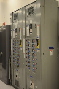
Main service panel and type of breakers
The main service panel is where the power is distributed throughout the building.
The main breaker at the top will cut the power to the entire building. All of the other breakers protect individual circuits. Be sure that all of the circuits are properly identified on the panel. This is necessary in case someone has to cut the power to one of the circuits.
For residential applications, the main breaker is normally a 100 amp breaker, but in the older units you will find many panels that have only a 60 amp main breaker. For commercial applications, amperages are much higher, and power brought into the building is usually three-phase.
NOTE: Never do any work in the panel. Only certified electricians are allowed to work in the panel. However, if the breaker trips off for some reason, you can re-set it.
![]()
Generator Transfer Switch
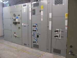
Main Breaker Panel
Fuses and Breakers
Fuses and breakers are referred to as “over current” protection devices. They guard the electrical system from damage by too much current. This can happen whenever wiring is overloaded by using too many appliances at the same time or by a short circuit caused by damaged wires.
A circuit breaker or fuse is inserted into each circuit at the service entrance panel. For correct protection the amperage rating of a breaker or fuse must be the same as the amperage rating of the circuit conductor it protects.
A circuit breaker serves both as a switch and a fuse. As a switch, a circuit breaker lets you open a circuit, therefore turn the breaker OFF whenever you have to work on a circuit.
As a fuse, it provides automatic “over current” protection. Inside the breaker a bi-metallic strip becomes a link in the circuit. Heat from excessive current will bend this strip, causing it to trip the breaker.
Most household branch circuits are protected with a 15 amp breaker but some circuits require larger breakers. Branch circuit breakers generally have the rating stamped on them.
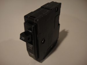
20 Amp residential breaker single pole
Circuit breakers can be reset (turned back on) once they have tripped. All circuit breakers are rated for specific amperage. As with fuses, the amp rating on the breaker must match the amp rating of the circuit it protects. An advantage of the breaker is that it acts as a time delay fuse. It will carry small overloads for up to 30 seconds, and large overloads, such as starting an electric motor, for several seconds.
There are three basic types of circuit breakers sold by different manufacturers:
- The first kind of breaker is similar to a switch, however when it trips you must push it all the way off and then push it on, in order to reset the breaker.
- The second kind is a double breaker with a bar connecting the two handles and is used to protect a 240 volt circuit.
- The third kind of breaker looks like a screw in fuse. When you look at it you will see a reset button in the center. This button is used to reset this type of breaker.
Electrical System Materials
It would be impossible to give a complete list of items or material that an electrician will install over the course of their career. What will be presented here will be a small sampling of the most commonly used material. As the trade and trade practices evolve over time you will see new products on the market as well. But this is a start.
Conductors
Conductors are the technical term for any equipment used to move current. This includes cables, single conductors or bus bars. They might be insulated or non-insulated. They could be armored or not. Sometimes they are buried in the ground, sometimes they are run exposed overhead. Each different type of conductor or assembly of conductors must be rated for the particular application that it is being installed in. Only if you are a journeyperson will you have the qualifications to select the proper conductor for the job.
Conductors are required to create a circuit and carry the current that will operate different devices or loads. Conductors are normally made of copper with a plastic or fibre insulating coating covering them so that they do not contact anything. Exposed wires are not only a safety concern, they are a problem in the circuit if they contact each other.
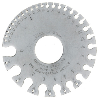
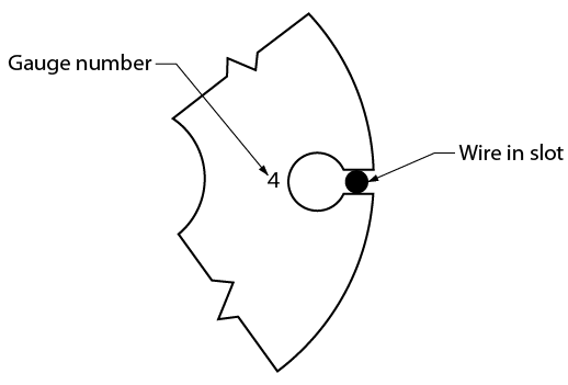
Conductors are rated according to the American Wire Gauge (AWG) system, which designates different gauges for wires of different thickness. Most conductors found in vehicles and equipment are braided multi-strand conductors because they can withstand vibration and motion better than solid conductors. Most wiring found in residential and industrial applications is solid conductors. Special measuring gauges are used to determine actual physical wire size.
Single Conductors
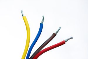
A conductor is normally shown on a wiring diagram by a straight line with a colour notation and often a gauge or size notation.
Single conductor wires range in size for the purposes of electrical installation. They can be as small as #18 and as large as 2000 kcmil. To give an example of those sizes, the smallest would be the size of a pencil lead and the biggest would be almost the size of a baseball bat.
- They can be solid or stranded, standard, flexible or extra flexible, annealed or non-annealed.
- They come in a variety of colours, red, black, blue and green being the most common but special orders can be ANY colour requested.
- They are either copper or aluminum, each having desirable properties and undesirable properties. Again, the selection of material can be very important.
Multi Conductor Cables
The sector in which you work will dictate the types of multi-conductor cables you will use.
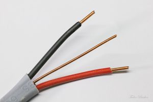
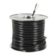
NMD90, sometimes called loomex, is used in wood framed buildings, usually residential. The acronym stands from non-metallic, dry, 90 degree ambient temperature. See image above.
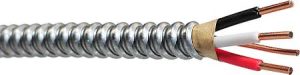
AC90, also called BX, is used in residential and commercial applications. It is found occasionally in an industrial application. The AC stands for Armoured Cable.
NMWU is used for underground installations, usually in residential applications. NMWU stands for non-metallic, waterproof, underground.
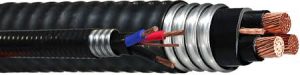
Teck Cable is used widely in the industrial world and occasionally in commercial applications. It is named from the Teck Cominco mine where it was first used.
Insulated cable is rarely used, when it is used it’s usually for fire protection systems.
Bus Bar
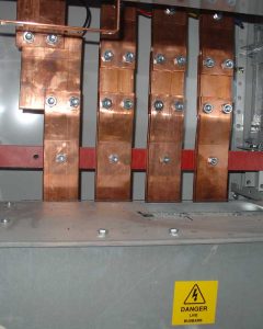
A bus bar is a metallic strip or bar (typically copper or aluminum) that conducts electricity within a switchboard, distribution board, substation, battery bank, or other electrical apparatus. Its main purpose is to conduct a substantial current of electricity, and not to function as a structural member. Bus bars may or may not be enclosed in a bus duct. Also, bus bars are important components in electrical power grid because they can reduce the power loss via reducing the corona effects. This is because bus bars have bigger surface areas compared to wires.
A corona discharge occurs where there is a very high voltage application. Normally, air is a good insulator, but if the voltage is high enough electrons will travel through the air causing a glowing effect and electromagnetic interference in communications devices. This is bad in energy transmission systems because it causes a waste of power. However, the effect is useful in photocopiers and x-ray machines.
Conduit

PVC conduit
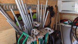
Various conduit and benders
Just like our examination of cables, there are many different types of conduit. You’ll work with sizes from 3/8” to 4” or possibly even bigger. They will attach to themselves and to boxes or equipment with different types of connectors.
Each family of conduit or raceway will have its own set of code rules to follow regarding support, bending radii, etc.
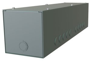
Boxes
Junction Boxes
Once again we’ll have to say that there are an almost innumerable number of junction boxes an electrician might install. There are certainly common ones though. 4” square deep boxes are very common in both shallow and deep designs. 4 11/16” box is used most commonly as a range or dryer receptacle box but can be used as a junction box if more room is needed. Other common sizes are 6” X 6”, 8” X 8”, 10” X 10”, and 12” X 12”.
The box should be chosen based on CEC section 12-3000. These rules tell us where a box can be installed and what size it must be to accommodate both wire size and bending radius of the wires. Pay close attention to this because, if an inspector refuses to pass the work, it’s a lot of work to remove and replace a junction box.
As with everything else that we’ve discussed so far, there are many different types of junction boxes. They are chosen to fit the location, the number and size of the conductors, the number and size of the conduit, the type of conduit, etc.
Most other junction boxes will be a variation of this. They come in many different dimensions. They aren’t always square either. Sometimes they contain terminal strips, other times they have lugs (also called a splitter box) and sometimes they are empty and used just for splices in the wire.
Device Boxes
<image boxes for commercial applications: f-clips, 220V, masonry, octagon, …>
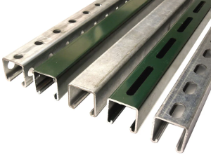
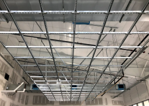
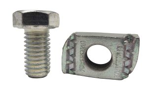
Unistrut
Unistrut is used almost everywhere in the electrical industry. Its versatility as a mounting method makes it invaluable when constructing racking systems.
Mounting, Supporting, and Securing Devices
Screws
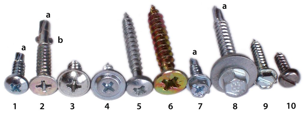
There are almost 30 different types of screw head designs commercially available. Each of these will have different sizes making well over 100. Not to mention the diameters and thread count or the type of material they are designed to fasten to. Certainly there are 1000’s of different types of screw. Some will have very specific purposes and other will be for general use.
There are definitely some screws that are more common than others.
Wood Screw
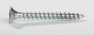
#8 wood screws are probably the most common. They have a pointed end and relatively coarse threads. They usually have a tapered head so they counter sink themselves into the wood. #8 refers to the diameter of the shaft.
Machine Screw
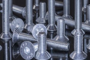
Machine screws end with a flat tip. They are screwed into holes that have been tapped or threaded in metal or plastic. Standard device boxes accept a #8 machine screw. Standard devices accept a #6 machine screw. #10 machine screws are also common. Really, they are a form of bolt with a head that accepts a screwdriver.
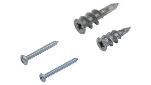
Self-Tapping Screws
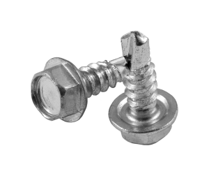
These screws are used on metal. They have a cutting end that drills a perfectly sized hole for itself and then taps its own threads as it’s driven into the metal. If they don’t have a drill end on them, you’ll find that they are very sharp at the point and their thread continues the entire length of the screw. The thread will catch and begin driving the screw into the material.
Concrete Screws
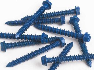
These are sometimes referred to as tap-cons. They are meant to be screwed into a predrilled hole. The threads are designed to bite into the concrete wall of the hole without stripping it out.
Inserts
Drywall Inserts
This type of insert has very coarse and wide threads. It is meant to be screwed into drywall and then have a wood screw driven into it. This maximizes the load bearing surface area.
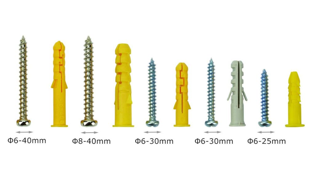
This type is often called a “Rawl” plug. They can also be used in concrete. A hole is made in the material you are inserting it into. The insert is then hammered into place and when a screw is screwed into it, the plastic flows away from the force of the screw and expands to form a tight fit.
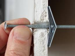
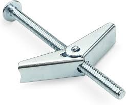
The toggle bolt is another type of drywall insert. A small hole is made in the drywall, just big enough to fit the compressed wings inside. The spring-loaded wings are then pressed together and inserted into the hole. Be careful not to drop the entire assembly into the hole. Then, with some backward pressure, the screw is turned until the wings press against the backside of the drywall. This can take some organizing as the toggle bolt must be attached to the thing that is being supported before the toggles are inserted.
Concrete Inserts
There are many different types of concrete inserts, also called anchors. They all rely on the same principle of compression though, either through a screw mechanism or by the use of a pinsetter and hammer. A hole is drilled of a size according to the size of the anchor being used. Check the manufacturer’s specifications for the right size (sometimes the package will even come with a hammer drill bit that is the right size). In the case of an anchor that requires a pin setter, you will now hammer the insert in and ‘set’ it. The equipment being anchored is then place and the bolts screwed in.
Threaded Rod
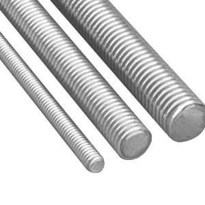
Also called ready rod, threaded rod is used with nuts to hang equipment or strut. It comes in many standard sizes. Most likely you will use 3/8” and 1/2″. It can be made of a variety of metal types including steel, galvanized steel and stainless steel.
Cable Ties
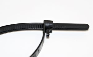
Ty-raps or zip ties are used to secure cables in place. It’s important to remember that they are considered a means to secure not as a means to support. This is one code rule often cited by inspectors who find it.
They come in variety of lengths, widths and colours. Again, you can order them in whatever colour you’d like. The most common though are white and black. White is for indoor use only as the UV rays from the sun can make them deteriorate. Black one can be used almost anywhere but both types will degrade over time. That’s another reason they can’t be used as a means of support.
Switches
Switches are used to connect and disconnect equipment from a power source. When you think of a switch you’ll probably think of a light switch. This is the one everyone is most familiar with. There are others though.
Residential switches come in any colour you can imagine. White and ivory are the most common though. They also come in various styles. Finally they are likely single pole 3-way, 4-way or timer switches.
Switches are rated according to the specific amperage and voltage they are suited for.
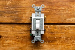
Single Pole Switch
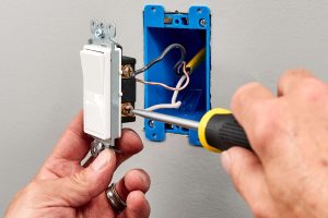
A single pole switch controls a light or receptacle from one location only.
Double Pole Switch
The double pole switch is similar to the single pole switch in as much as it controls a light or receptacle from one location only.
The double pole switch can be wired so that it can switch receptacles and appliances that use 240 volt circuits.
Three Way Switch
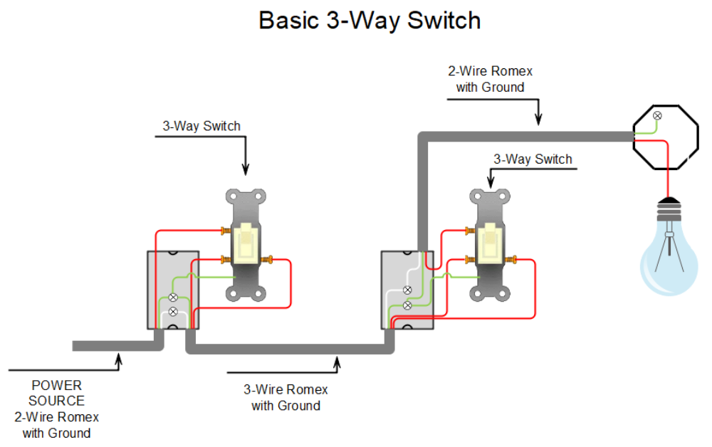
Three way switches are identified by three terminals and a plain toggle.
Three way switches operate in pairs to control a light or a receptacle from two locations.
Four Way Switch
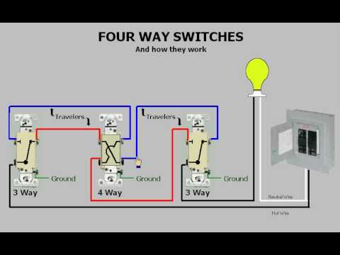
Four way switches can be identified by four terminals. They will have marking such as “in” and “out”. Four-way switches are used in conjunction with three-way switches to allow lights to be controlled from three or more locations.
Dimmer Switch
This switch allows you to vary the lights from dim to bright and from bright to dim. Dimmer switches are available in different styles.
Note: a special switch is required for fluorescent lights.
Do not use with ceiling fans.
Receptacles
In the residential sector you will find standard or “Decora” styles of receptacles. Mostly 120V 15A plugs will be used although occasionally you’ll find 120V 20A or 240V receptacles as well (ranges and dryers). You will also see Ground Fault Circuit Interrupting receptacles outside and in bathrooms. Rarely, you will find a surge suppressor receptacle.
In a commercial environment you’ll find the same types of plugs. Additionally, you may see isolated ground receptacles. Finally, on an industrial site you’ll find welding receptacles and other, large load, receptacles.
<images including isolated ground and other commercial>
Sample Receptacles
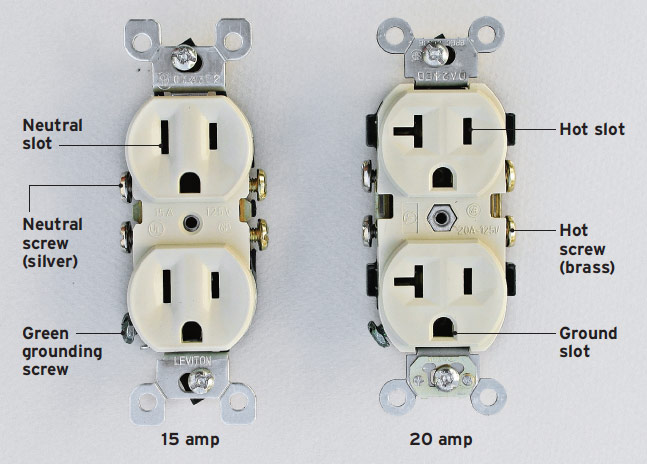
All receptacles are rated for a specific amperage and voltage.
Grounded duplex receptacles have two outlets which have three slots.
One of the two parallel slots is larger than the other. This bigger slot is the neutral and the smaller slot is the hot. The U shaped slot is for the grounding prong. The ground prong on a plug is longer than the other prong.
20 amp receptacles are easily distinguishable from 15 amp receptacles by the shape of the slots.
It is possible to have the outlets of a duplex receptacle wired to different circuits. To make the outlets operate separately remove the break off tab that connects them.
Non-grounded duplex receptacles are still available for renovations.
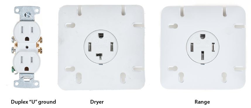
Special Receptacles
These special receptacles are designed differently so that only a specific plug will fit a specific socket.
Examples of these types of receptacles are your dryer plug, range plugs and air conditioning units.
Ground Fault Circuit Interrupter
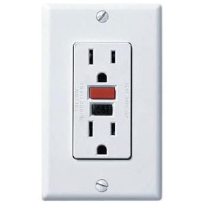
The ground fault circuit interrupter (GFCI or GFI) is a device that protects you from electric shocks caused by excess moisture. The purpose of the GFI is to detect the moisture and trip the breaker. A GFI checks the amount of current going to and coming from a receptacle, or circuit. Whenever the amounts of incoming and outgoing currents are not equal – indicating a current leakage (a ground fault) the CFI opens the circuit instantly, cutting off the electricity. GFI’s are built to trip in 1/40 of a second in the event of a ground fault of 0.005 ampere.
The GFI is re-set by pushing the re-set button in the middle of the device.
Circuit Protection Devices
Protection is required to prevent damage to expensive components and all the equipment wiring if a circuit should overload due to excessive current flow. Protection can be provided by:
- fuses
- fusible links
- circuit breakers
- thermal limiters
Fuses
The fuse is the most common circuit protection device. Fuses are available in different shapes and sizes and are rated to burn out or blow out at a specific amount of current flow. The material within the fuse provides excellent conductivity as long as the current flow stays below the rating of the fuse.
Once the current flow exceeds the rating, the material will melt and open the circuit. Blown fuses indicate a circuit fault that must be located and repaired. Simply replacing a burned fuse will not correct the problem. A burned fuse should never be replaced with another fuse that has a higher rating than what is recommended by the manufacturer.
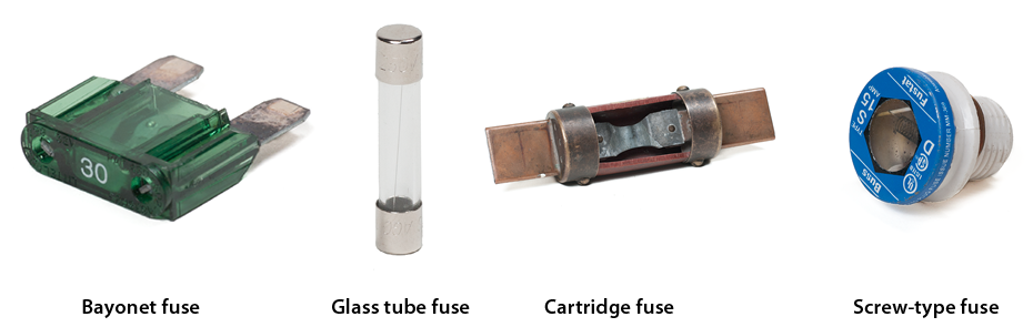
Fuses can be located in a fuse box or in-line in a special holder. Small fuses, such as the glass tube fuse, are available in different lengths and sizes and have the amps rating printed on the end. Bayonet-type fuses are colour coded and have the amperage rating printed on the case. Larger cartridge fuses are used in high-voltage industrial applications. Plug or screw type fuses have a clear window on the face to check them. The figure below shows these four types of fuses.
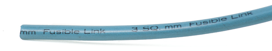
Fusible Links
Fusible links are special wires designed to burn out and open the circuit if the current flow exceeds the rated amount. These links are normally crimped into sealed connectors within the circuit. There should be a four-gauge difference between the conductors they protect. If the conductor is 16 gauge, the fusible link must be 20 gauge. Fusible links can be identified by a colour code or by a large insulation block with the gauge cast into the surface. They cannot be replaced with regular conductors.
Circuit breakers
Circuit breakers are used in circuits that may have temporary overloads and must be restored to service quickly without permanent disruption. Headlight circuits are a typical low-voltage circuit that use a circuit breaker. Residential wiring for 120 and 240 volt systems also use circuit breakers.
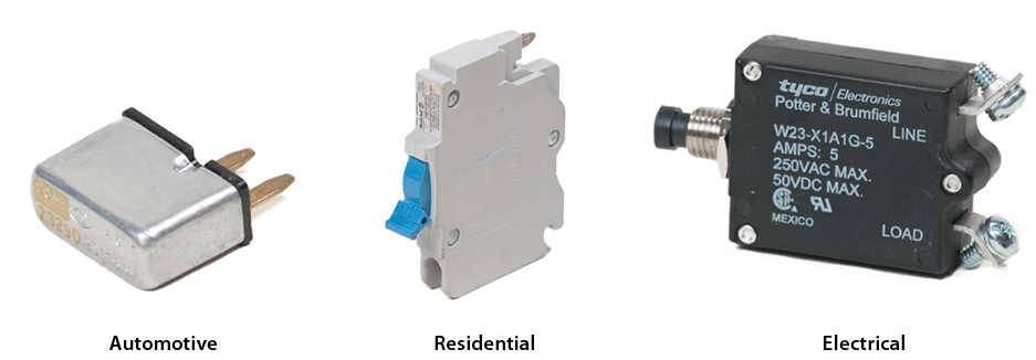
There are three different types of circuit breakers:
- cycling
- non-cycling
- manual reset
Cycling circuit breaker
Cycling circuit breakers contain an arm constructed of two different types of metal: one that expands quickly when heated and one that expands more slowly. This allows the circuit breaker to cycle from open to closed automatically.
There is a contact point attached to one end of the arm that provides a closed circuit when it touches a fixed contact. If the current is too high for the circuit, the arm will heat and begin to bend, lifting the movable contact away from the fixed contact to open the circuit. When the arm cools, it will straighten out and touch the fixed contact again, closing the circuit.
This is the type of circuit breaker that is used in automobile lighting systems.
Non-cycling circuit breaker
Non-cycling circuit breakers use a high-resistance wire around the arm that will carry current when the contact points open. This provides heat that prevents the circuit breaker from cycling. To reset this type of circuit breaker, it must be disconnected from the power source so that the arm can cool.
Manual reset circuit breaker
Manual reset circuit breakers must be reset by pushing a button or reset bar. They will not cycle automatically. This type of circuit breaker is used in residential wiring.
Thermal limiters
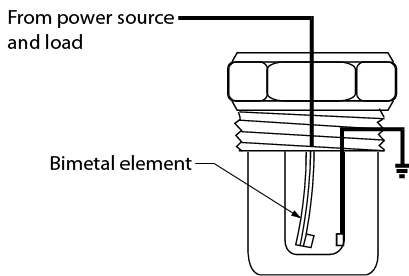
Thermal limiters are designed to melt if the device they are protecting exceeds a pre-set temperature. For example, the heating elements in a 120 volt portable electric heater are protected by a thermal limiter. If a thermal limiter melts, it must be replaced, just like a fuse.
Circuit Control Devices
Controlling a circuit is an essential part of the electrical system. The control devices will turn circuits on and off as well as limit the conditions within the circuit, including amperage and voltage.
Circuit control devices include:
- resistors
- switches
- relays
- solenoids
Resistors
Resistors are used in circuits where full current flow may not be required. One side effect of resistors is that they produce heat. There are three common resistors found in most circuits:
- fixed
- stepped
- variable
Fixed resistors
Fixed resistors restrict current flow or voltage and are connected into the circuit or built right into a component.
In some cases, this resistance is provided by wires. These are special wires that can be identified by markings that state “resistor wire—do not cut or splice.”
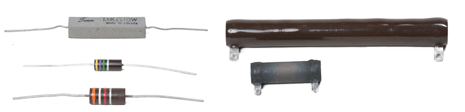
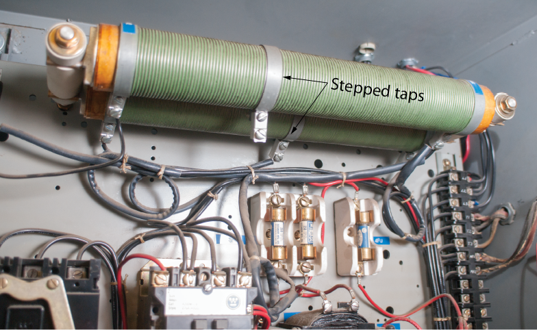
Stepped resistors
Stepped or tapped resistors have more than one fixed value and are connected into the circuit by wiring and a switch. The control system on a fan is a good example of one use for this type of resistor. By selecting different fan speeds with the switch, current will flow through different resistances and provide different fan motor speeds.
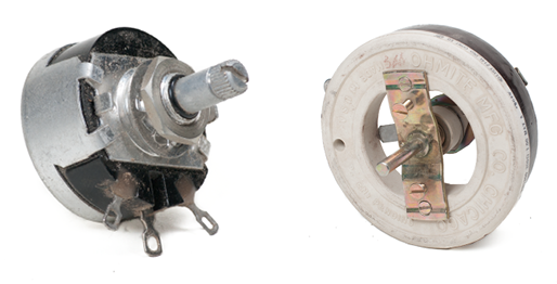
Variable resistors
Variable resistors include potentiometers and rheostats. A variable resistor is called a rheostat when it is used to control current. A variable resistor is called a potentiometer when it is used to control voltage.
A rheostat has two connections and a movable wiper that contacts a winding. If the wiper is close to the power connection, there is high current flow. As the wiper is moved away from the power connection, the resistance in the circuit increases and the current drops.
A potentiometer has a winding that is in series rather than being open ended. Each end of the winding has a terminal for connection into a circuit, as does the movable arm. The movable arm provides an output voltage that varies from full source voltage to zero voltage as it moves along the winding.
Switches
Switches are the most common control device for electrical circuits. Switches are operated manually, hydraulically, electrically, or pneumatically. Switches operate a circuit by opening or closing the circuit.
Switches have different numbers of inputs, called poles, and different numbers of outputs, called throws. The most common switch is the single pole, single-throw switch (SPST).
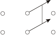
A switch that can make more than one contact is called a single-pole, double-throw switch (SPDT). A slide switch, rocker switch and a toggle are shown in Figure 9.
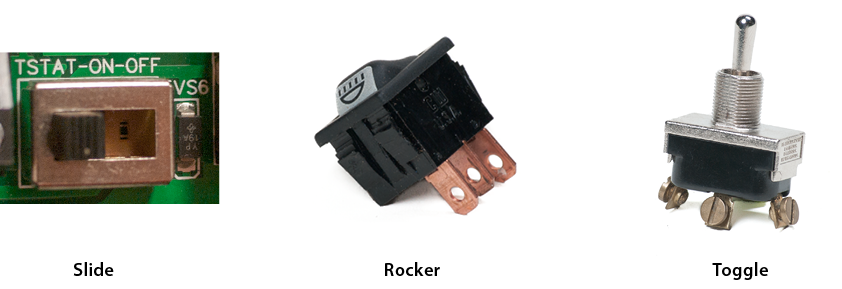
Slide, rocker, and toggle switches
If more than one switch is operated by the same control, it is called a gang switch. The arrangement of the fixed contact positions (called throws) and the moving contact (the pole), can be seen in the schematic symbol. It is called a double-pole, double-throw switch (DPDT).
Another type of switch is the pushbutton switch. This type of switch can be used in different configurations, including SPST, SPDT, and DPDT.
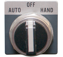
A rotary switch has a single pole and two positions.
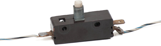
Momentary contact switches require the operator to maintain pressure to keep the circuit open or closed, because the operating button is spring-loaded and will return to its at-rest position when released. A typical application is a horn switch.
Temperature, pressure, and motion switches
A temperature-sensitive switch operates on the same principle as a cycling circuit breaker to make and break an electrical connection. These switches are called flashers and can be used to operate turn signals or emergency lights. In this type of switch the heater is included as part of the switch.
Other temperature-sensitive switches can be used to turn current flow on or off for operations such as cooling fans or electric defrosters. They sense the temperature of the engine or outside air and control the circuit by using a bimetal strip and contacts.
Pressure-sensitive switches can sense the pressure in a pneumatic or hydraulic system and turn electrical devices on and off. These are used for electrical clutches in air conditioning, air pumps, and other similar systems.
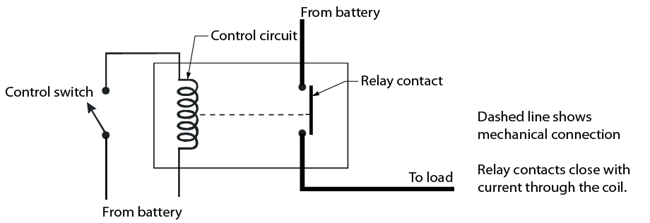
Relays
Relays are electrically activated switches that allow a very small current flow to control a large current flow. Every relay has a power circuit and a control circuit. The control circuit is energized by a switch and consists of a soft iron core with a wire winding.
When current flows through the winding, an electromagnetic field is created, that pulls an armature down to close contacts in the circuit. A typical application is a starter relay.
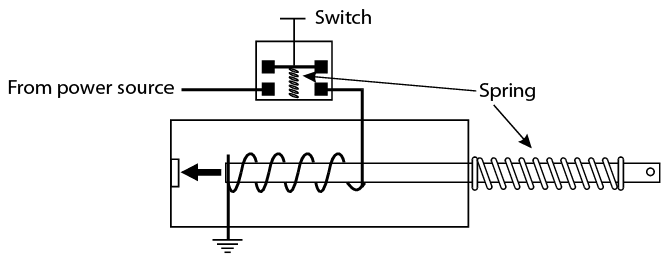
Solenoids
A solenoid is an electromagnet with a movable core that changes electrical energy into mechanical force. Some solenoids may activate contacts and act as a relay, such as in a starter solenoid.
Transformers
The transformer shown in Figure 20 is used to increase or decrease voltage in an electric circuit. Transformers are rated in volts and amps for specific applications. A typical application is a doorbell circuit, transforming 120 volts AC to 24 volts AC.
![]()
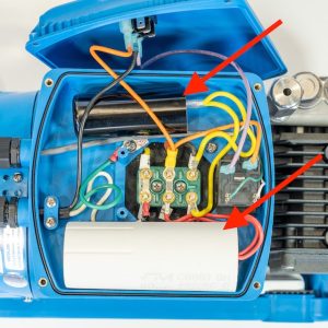
Capacitors
Capacitors are devices used to absorb and store electric current to prevent damage to components. These components are made of two conductor plates with a non-conducting material between them. Capacitors will store energy if the circuit is broken and will remain charged until the circuit is restored.
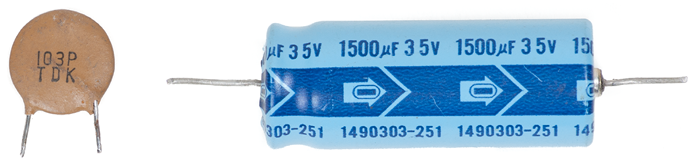
Capacitors are useful for absorbing stray currents and preventing arcing across opening contacts. Variable capacitors are called trimmers or tuners and are used only in very sensitive circuits with low current flow.
Motors quite often have a start capacitor to give the motor a ‘kick’ to start moving. It is possible start capacitors would need to be replaced (if a motor is ‘humming’ but not moving) but this is not something a maintenance worker would do. This image shows a start capacitor in an electric induction motor.