10 Electrical Measurements
Introduction to voltage measurements
Voltage measurements are very easy to make with a DMM. On meters with manual range selection, start with a value one setting higher than expected. An autorange DMM will automatically select the range based on the voltage present. Figure 4 shows the process.
Note:
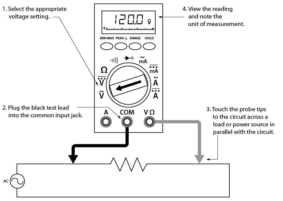
4. Using a DMM to measure voltage
Follow these steps to measure voltage:
- Select the DC or AC volts function by turning the function switch to DC or AC volts.
- Plug the test probes into the appropriate probe jacks.
- Connect the tips of the probes across the source or load.
- View the reading on the display unit. Be sure to note the unit of measurement. If you are testing DC voltage and a negative sign appears in the display, the polarity of yourprobes is incorrect and needs to be reversed.
 Use the one-hand technique. Attach test leads one at a time using only one hand. Whatever you choose to do with your other hand, keep it well away from a live circuit or associated equipment. Avoid holding test leads in both hands. The one-hand technique decreases the possibility of a dangerous electrical shock by reducing the chance of current flowing through your body across your chest.
Autoranging units display the unit of measurement in the top right corner (annunciator). In manual ranging units, the meter will use the range selected. Autorange will determine the highest setting and automatically display that unit.
IMPORTANT: When using the one hand technique, it is very important to you specialized clamping leads or attachments.
This often involves clamping one lead of the multimeter to a reference point, such as ground or neutral, while using the other lead to make measurements at live points in the circuit. To achieve this, specialized clamping leads or attachments are sometimes used with multimeters. These clamps can securely attach to the reference point, allowing the worker to free up one hand for other tasks, such as manipulating components or taking notes. One hand holds a probe on a reference point such as ground or neutral, (if using a clamping lead, it needs to be held in place to ensure it remains clamped to the reference point) the other hand holds the second probe to move along the live points being tested.
Ensuring proper safety measures, including appropriate personal protective equipment (PPE) and adherence to safety protocols, is crucial when working with electrical systems, especially when making measurements in live circuits.
Introduction to current measurements
As you have seen, the placement of meter leads for voltage measurements is straightforward. The leads are simply connected across, or in parallel with, the points of voltage to be measured.
For current measurements, however, the process is slightly more complex. First, the circuit must be opened at the test points and the meter inserted in series at that opening (Figure 5). The total current must flow through the meter. To allow the measurement to be made without disturbing the circuit itself, the current meter must have very little internal resistance.
This is where the beginner must be particularly alert. If the meter is inadvertently connected across a P.D. (potential difference) or in parallel with a component instead of in series, the small internal resistance will permit a very large current to flow through the meter. This will most certainly damage the meter severely and perhaps the circuit as well.
With current measurements, shutting off the power before connecting the meter is essential. You will be disconnecting one end of a wire or component in order to connect the meter in series. If you leave the power on, you could easily receive a dangerous shock or do damage to the circuit.On meters with manual range selection, start with the highest current setting and work your way down.
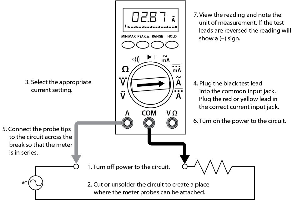
- Using a DMM to measure current
Current measurement procedures
Follow the steps below to measure current:
- Turn off the power to the circuit that will be measured.
- Open the circuit by disconnecting or unsoldering a connection at a point where you wish to measure current.
- Select the DC or AC amps function by turning the function switch to DC or AC amps.
- Plug the test probes into the appropriate probe jacks. Note that the jacks used may not be the same ones used to measure volts.
- Connect the tips of the probes across the break in the circuit as shown in Figure 6 so that the current to be measured flows through the meter. Note that this is a series connection. Never connect the ammeter in parallel with the source or load, as this will cause a short circuit and damage the meter.
NOTE: Non-clamping multi-meters are restricted to 10 amps or less (depends on the meter) for measuring current in a circuit.
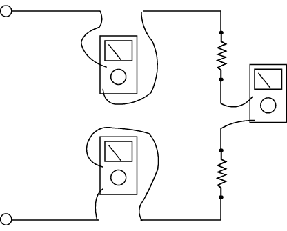
- Ammeter connections to measure the same current at different points in a circuit
- Turn the circuit power back on.
- View the reading on the display unit. Be sure to note the unit of measurement.
- Switch power off and disconnect meter leads from the circuit.
- If testing is finished at this test point, restore the circuit by reclosing the connection. When current measurements are complete, turn the function switch to the OFF position and remove the test leads.
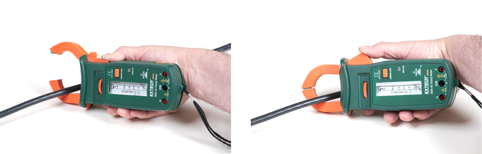
Some types of DMMs have a clamp-on ammeter or tong tester. These ammeters have two spring-loaded expandable jaws that allow you to clamp around a single conductor (Figure 7). This feature allows you to measure the magnetic field created by the current flowing through the wire to give an ampere reading without having to make physical contact or disconnect the circuit.
- Using clamp-on ammeter
Introduction to resistance measurements
You have studied voltage and current measurements, but you will find resistance measurements different in several ways. Resistance is measured with the circuit’s power turned off. The ohmmeter sends its own current through the unknown resistance and then measures that current to provide a resistance value readout.
Role of the battery
Even though it reads out resistance, the ohmmeter is still a current-measuring device at heart. The ohmmeter is created from a DC current meter by the addition of a group of resistors (called multiplier resistors) and an internal battery. The battery supplies the current flow that is eventually measured by the meter. For this reason, use an ohmmeter only on dead circuits.
In the process of measuring resistance, the test leads are inserted in the meter jacks. The leads are then attached to the ends of whatever resistance is to be measured. Since current can flow either way through a pure resistance, there is no polarity requirement for attaching the meter leads. The meter’s battery sends a current flow through the unknown resistance, the meter’s internal resistors, and the current meter.
The ohmmeter is designed so that it will display 0 Ω when the test leads are clipped together (zero external resistance). The meter reads infinite (I) resistance or over limit (OL) resistance when the leads are left open. When a resistance is placed between the leads, the readout increases according to how much current that resistance allows to flow.
To conserve its battery, an ohmmeter should never be left on the ohms function when not in use. Since the current available from the meter depends on the state of charge of the battery, the DMM should be zero adjusted to start. This may require no more than a test of touching the two probes together.
Note: Figure 8 shows how resistance measurements are taken.
1000 Ω = 1 kΩ
1 000 000 Ω = 1 MΩ
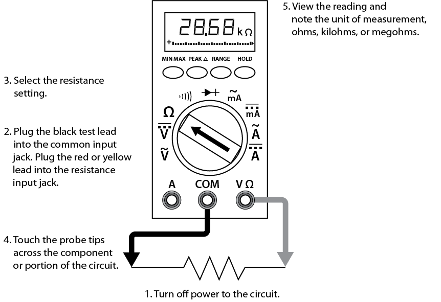
- Using a DMM to measure resistance
Resistance measurement procedures
Follow the steps below to measure resistance:
- Turn off the power to the circuit. Remove or isolate the component to be tested.
- Plug the test probes into the appropriate probe jacks. Note that the jacks used may be the same ones used to measure volts.
- Select the ohms function by turning the function switch to ohms. Start with the lowest setting.
- Touch the probes together to check the leads, connections and battery life. The meter should display zero or a very small amount of resistance for the test leads. With the leads apart, the meter should display OL or I, depending on the manufacturer.
- Connect the tips of the probes across the break in the component or portion of the circuit for which you want to determine resistance. If you get an OL (over limit), move to the next level.
- View the reading on the display unit. Be sure to note the unit of measurement.
- After all the resistance readings are complete, turn the DMM off to prevent the battery from draining
To measure the resistance of components in a circuit, disconnect all but one load. This prevents loss of correct orientation when reconnecting.
You can use the same connection procedure to verify that a circuit, wire, fuse, or switch is complete with no open. This is called a continuity test, and most DMMs will have an audible continuity setting (
 ). If there is no audible alarm, then the circuit is broken or there is too much resistance. A good example is testing a heating element when the element is burned out.
 Now complete the Learning Task Self-Test. It is ungraded and resets upon refreshing page.