4 Electrical Circuits
Learning Objectives
Describe the Properties of Electrical Circuits
The term circuit refers to a circular journey or loop. In the case of an electrical circuit, it is the closed path or loop travelled by the electrons. The movement or flow of electrons (current) is predictable and measurable, depending on a number of variables within the circuit.
Polarity
Electrical polarity (positive and negative) is present in every electrical circuit. Electrons flow from the negative pole to the positive pole. In a direct current (DC) circuit, one pole is always negative, the other pole is always positive, and the electrons flow in one direction only. In an alternating current (AC) circuit, the two poles alternate between negative and positive, and the direction of the electron flow reverses.
Conventional Theory
In conventional electrical theory, the movement of positive and negative charges is described based on the concept of conventional current flow. According to this convention:
- Conventional Current Flow:
It’s assumed that current flows from the positive terminal of a voltage source to the negative terminal. This convention was established before the discovery of the electron and is based on the observation that in many circuits, such as those involving metal conductors, positive ions in the material move relatively little compared to the movement of electrons. So, while electrons actually move from the negative terminal to the positive terminal, conventional current is described as flowing in the opposite direction, from positive to negative.
- Electron Flow:
Electrons, which are negatively charged particles, are the primary charge carriers in most electrical conductors. They move in response to an electric field, such as the voltage applied across a circuit. When a voltage is applied across a conductor, electrons drift in the direction opposite to the conventional current flow, i.e., from the negative terminal of the voltage source to the positive terminal.
- Positive Charge Movement:
In certain situations, such as in electrolytes or in semiconductors where positive charge carriers (like holes in p-type semiconductors) are predominant, conventional current flow still applies. This means that in these cases, positive charges move in the direction of conventional current flow (from positive to negative).
In summary, conventional electrical theory uses the concept of conventional current flow, where current is described as flowing from positive to negative, even though the actual movement of charge carriers (such as electrons) is in the opposite direction. This convention simplifies circuit analysis and is widely used in electrical engineering practice.
Circuit components
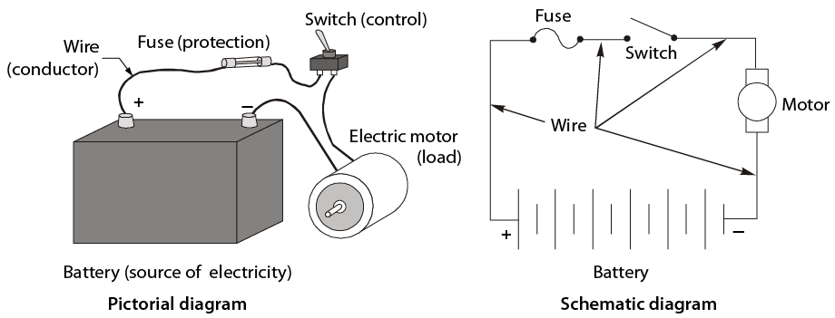
A closed circuit provides a complete path for the flow of electrons through conductors. Included in this circuit there must be a resistance (or load), which will do the work and some form of control. For a circuit to be operational it must contain some basic components (Figure 5). These include:
- power source
- conductors
- controls
- load
- protection
Power source
In equipment, the power source is the battery when the engine is off and the generator when the engine is running. In most buildings, it is the power supplied by the local service provider.
Conductors
Conductors are wires or cables wrapped in insulation that carry the current in the circuit. A common ground circuit conductor could be the frame or body of the equipment or the frame on a vehicle.
Controls
Switches are used to turn the current on and off or to regulate the flow of electricity. Switches can be operated mechanically by vacuum, pressure, or electricity.
Load
The load converts electrical energy to work, such as with electric motors, bulbs, heater coils, or horns.
Protection
Fuses, circuit breakers, or fusible links must be used to prevent damage to the source, load, and conductors.
Basic circuit
In order for electricity to flow, a circuit must fulfill two basic requirements:
- The circuit must be closed. This means that the switch must be closed, the circuit protection device must be in good condition, the load must be in working order, and the conductors must be intact. Any break in the system will prevent operation.
- A voltage source, such as a battery, must be available. The battery must be fully charged and capable of supplying electrical power.
Electrical units
To move electrons through a conductor, energy is required in the form of potential energy difference. This potential difference acts like a pushing force or pressure moving the electrons through the circuit. When you say that a battery has 12 volts, you are really saying that it has an electrical pressure of 12 volts. Pressure in an electrical system is also known as potential difference or electromotive force. This is measured in volts (V), which are named after the Italian physicist and chemist Alessandro Volta.
Current flow in a conductor indicates the volume of electrons in motion past a single point. The rate of electron flow is measured in amperes (A), named after the French physicist and mathematician André Ampère.
Just as friction opposes motion around you, there is an electrical quantity that opposes or resists the flow of electric current. This amount of resistance in an electrical circuit relative to the movement of electrons is measured in ohms (Ω), named after the German physicist Georg Simon Ohm.
Ohm’s law
One volt of electrical pressure will push one ampere of electric current through one ohm of resistance. This means that the current in a circuit is directly proportional to the voltage and inversely proportional to the resistance.
This relationship is known as Ohm’s law and can be written in the form of an equation:
E = I × R, where:
Volts (V) is represented by “E” for electromotive force.
Amperes (A) is represented by “I” for intensity of current.
Ohms (Ω) is represented by “R” for resistance.
This formula can be changed to find any missing value. For instance, if you know resistance and voltage but need the value of the current, then the formula would read:
I = E / R
If you know the voltage and the current but need to find the resistance, then the formula would read:
R = E / I
The easiest way to do this is to place the formula in a circle (Figure 6). Then, to find the formula you need, just cover up the missing element.
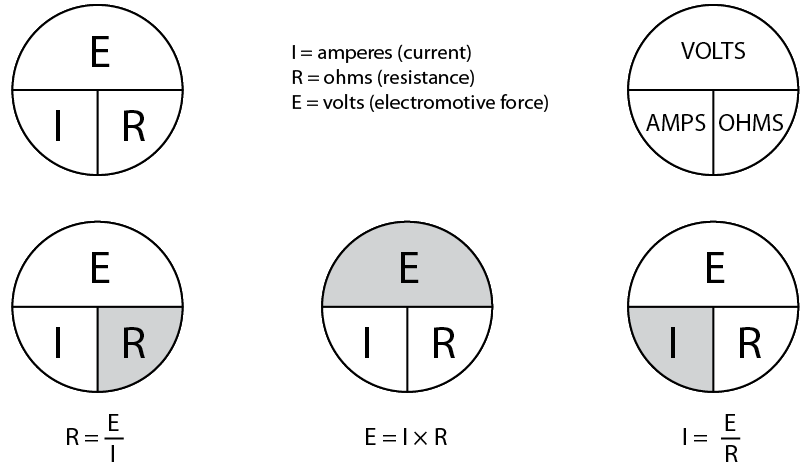
Ohm’s law circuit aid
Measuring electricity
The system used to indicate electrical quantities is as follows:
- milli, meaning times one one-thousandth or 0.001 (1/1000), symbol m
- micro, meaning times one one-millionth or 0.000 001 (1/1 000 000), symbol μ
Quantities larger than 1:
- kilo, meaning times 1000, symbol K
- mega, meaning times 1 000 000, symbol M
Examine the following comparisons of quantities:
- 15 mA = 0.015 A
- 500 mA = 0.5 A
- 650 mV = 0.65 V
- 50 μA = 0.000 05 A
- 700 μV = 0.000 7 V
Try to solve the following questions with calculations using Ohm’s law.
- If a circuit has a current flow of 3 A and a pressure of 12 V, what is the resistance?
The formula is R = E ÷ I.
Therefore R = 12 V ÷ 3 A.
The result is R = 4 Ω.
- If resistance in a circuit is 10 Ω and the pressure is 12 V, what is the current flow?
The formula is I = E ÷ R
Therefore I = 12 V ÷ 10Ω.
The result is I = 1.2 A.
- If a circuit has a current flow of 2 amps and the resistance is 20 ohms, what is the pressure in volts?
The formula is E = I × R.
Therefore E = 2 A × 20 Ω.
The result is E = 40 V.
Power
When work is done on an object, the object receives energy. So power (P) can be defined as the rate of doing work, or as the rate of energy transfer.
The power level that a load performs at (for example, a heater fan motor) is measured in watts (W), named after James Watt, the Scottish engineer. This is the measure of a load’s ability to convert electrical energy to another form of energy, or the rate of energy transfer. Electrical power is calculated by using the formula
watts = volts x amps
or
P = E × I.
This formula can be changed to find any missing value. For instance, if you know power and voltage but need the value of the current, then the formula would read
I = P / E.
If you know the power and the current but need to find the voltage, then the formula would read
E = P / I.
The easiest way to do this is to place the formula in a circle (Figure 7). Then, to find the formula you need, just cover up the missing element.
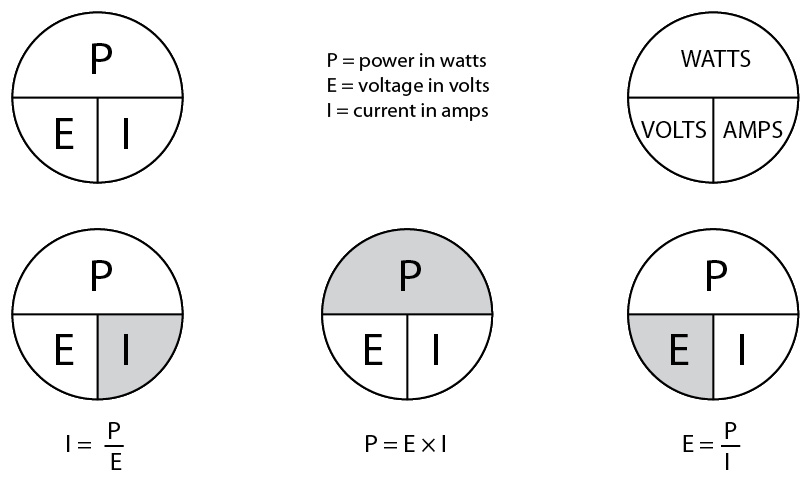
Power circuit aid
Try to solve the following questions for power, using Ohm’s law calculations.
- How many amps will flow through a 96 W headlight bulb in a 12 V system?
The formula is I = P ÷ E.
Therefore I = 96 W ÷ 12 V.
The result is I = 8 A.
This could be an important consideration in selecting the correct circuit protection device. A fuse with a rating of more than 8 A would have to be chosen in this situation.
- How much power will a soldering gun produce if it uses 6 A in a 120 V electrical system?
The formula is P = E × I.
Therefore P = 120 V × 6 A.
The result is P = 720 W.
Soldering guns are rated in watts. The higher the wattage rating of the gun, the more heat it will produce.
Source: B.C. Campus Line E – Electrical Fundamentals Competency E-1 available for free at https://collection.bccampus.ca/textbooks/line-e-electrical-fundamentals-competency-e-1-describe-the-basic-principles-of-electricity-bccampus-228/