7 Electrical Circuits- Parallel Circuits
Parallel Circuits
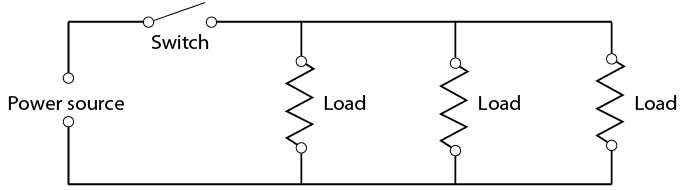
The parallel circuit (Figure 5) has completely different characteristics. In a parallel circuit, two or more loads are connected side by side and are controlled by one or more switches. The different loads can each have their own switch, but the major difference is that each of the loads has access to the same amount of voltage and can operate independently of the others. There is more than one path through which the current can flow.
Parallel circuit
If one of the loads fails, the others will continue to operate. This is very important in a circuit such as headlights and parking lights, where failure of one bulb does not cause the entire circuit to fail.
Key Takeaways
Parallel circuits have the following operating rules:
- Total resistance in a parallel circuit is always less than the smallest resistor in the circuit.
- Total current flow is equal to the sum of the current flow through each load.
This may seem surprising after you observed the operation of a series circuit, but this is one of the advantages of a parallel circuit. Since each load operates independently, each load will get full voltage and use whatever current it requires. The current can be calculated using the assumed voltage method.
Example
If you have a circuit with 2 Ω, 4 Ω, and 6 Ω, just pick any convenient voltage. In this case, 12 V would probably work well.
Perform the following calculations:
- Use Ohm’s law determine the current flow through each of the individual loads. Remember that the formula states that I = E ÷ R.
for the first resistor I = 12 V ÷ 2 Ω
I = 6 Afor the second resistor I = 12 V ÷ 4 Ω
I = 3 Afor the third resistor I = 12 V ÷ 6 Ω
I = 2 A - They will each use as much current as they require to operate because each load gets all the voltage. According to the rules of parallel circuits, the total current flow in the circuit is equal to the sum of the individual current flows.
IT = 6 A + 3 A + 2 A
IT = 11 A
- Therefore, the total resistance (RT) of the circuit according to Ohm’s law, R = E ÷ I.
R = 12 V ÷ 11 V
R = 1.09 Ω
In this example, the total resistance in the circuit is very low and the total current flow is very high. This is useful to provide bright lights and individual light operation in circuits such as those found in head light systems. In addition to head lights, examples of this circuitry include marker lights as well as front and rear parking lights. All of these are turned on by one switch but operate independently.
Solving for unknown values
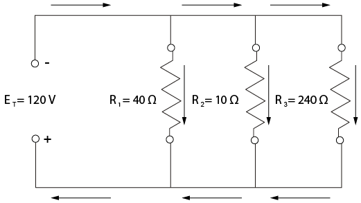
Ohm’s law can be applied to each part of a parallel circuit as well as to the entire circuit. Figure 6 represents resistors of 40 ohms, 10 ohms, and 240 ohms connected in parallel to a 120 volt supply. The arrows in the drawing represent the direction of the electron flow.
Parallel circuit
Since each resistor or load acts as an independent circuit, each resistor receives the entire voltage of the supply.
The voltage across each path in a parallel circuit is equal to the total voltage of the circuit, so:
ET = E1 = E2 = E3 …
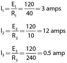
Using the formula above you can now find the current in each path. Since the voltages across each component in a parallel circuit equal the total voltage, using Ohm’s law:
The total current in a parallel circuit is equal to the sum of the currents in the individual paths:
IT = I1 + I2 + I3 …
The total current in the circuit shown in Figure 6 is equal to:
IT = 3 + 12 + 0.5 = 15.5 amps
Calculating resistance in a parallel circuit
Total resistance in a parallel circuit can be found using any of four different methods.
Method 1
If the total circuit voltage and total circuit current are known, the total resistance can be found using Ohm’s law. For the circuit shown in Figure 6:
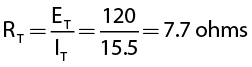
The total resistance in a parallel circuit will always be less than the value of the smallest resistance in that circuit. Use this rule of thumb as a quick check when calculating parallel circuits. In this example, 7.7 ohms is smaller than 10 ohms, the smallest resistance in the circuit.
Method 2
If only the resistance values of a parallel circuit are known, the total resistance of the parallel circuit can be found using this formula:
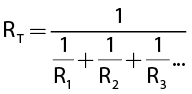
In the circuit shown in Figure 6:
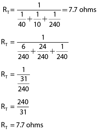
This formula can be solved mathematically using fractions or by using the reciprocal function of your calculator. If you are having trouble using this formula, contact your instructor for assistance.
Method 3
If the resistance values of each of the paths are known and are the same value, the total resistance of the circuit can be found by dividing the value of one resistor by the number of resistors (Figure 7).
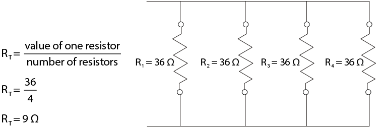
Parallel circuit with four resistors
Method 4
You can solve for the total resistance of any two resistors (Figure 8) using the product-sum method:
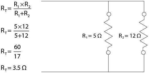
Parallel circuit with two resistors
Adapted from: B.C. Campus Line E – Electrical Fundamentals Competency E-1 available for free at https://collection.bccampus.ca/textbooks/line-e-electrical-fundamentals-competency-e-1-describe-the-basic-principles-of-electricity-bccampus-228/