11 Analyze Circuits
The trick to effective troubleshooting electrical equipment and circuits is to zero in as quickly as possible on the problem. Using an electric meter will allow you to effectively test the components that are most likely to be the cause of the problem before you unnecessarily dismantle the equipment and replace parts.
Safety
Even though you may normally deal with small voltages and currents, the values are never far away from lethal levels. You can receive a shock or burn from any common electrical circuit. The severity of the electrical shock depends on a number of factors:
- the amount of current that passes through the body
- the path that the current takes through the body
- type of voltage—AC or DC
- voltage strength
- the length of time that the current flows within the body
- condition of the skin and the body’s chemical makeup
- area of contact
Normal household current (plugs and light circuits) is generally limited by a circuit breaker to a value of 15 amperes. This device has been designed to trip and open a circuit if the 15 ampere value is exceeded, and it is designed to protect against property damage. It is possible to cause a fatal injury with a current flow of only 50 milliamperes (mA) or five one-hundredths of an ampere. The body is sensitive to relatively small values of current. In comparison, a 100 watt lightbulb draws approximately 0.85 ampere (850 mA) of current when connected to a 120 volt source. Remember, there are 15 amperes available in each standard house circuit.
Electrical shocks, electric burns, and other related injuries occur far too often and in most cases go unrecorded. If an accident happens:
- Don’t touch the person and don’t use a conductive tool to free the person that may be electrically energized.
- Shut off the power or pull the plug if it is safe to do so. If you are not able to, get help.
- Remove the person from the contact point using a non-conductive object such as a dry piece of wood or a leather belt.
- Call 911 for help if the person is obviously injured (loss of consciousness, significant trauma, etc.)
- Seek medical attention (first aid) in any case of injury such as an altered mental state (confusion, slow/slurred speech) or other obvious injury (laceration, burn, etc.).
When performing maintenance or doing repair work, or when a machine is in an unsafe state, it is vital to eliminate the possibility of the machine being energized unexpectedly. In order to create a safe work environment, workers need to guard against contact with electrical voltages and control electrical currents.
Make the environment safer by doing the following:
- Protect portable electrical equipment with an approved ground-fault circuit interrupter (GFI) when using the equipment outdoors.
- Ensure all the cords are in good condition, with the caps and plugs well secured on the cables. Ensure the proper U-ground plug is in good working condition.
- Use cords of sufficient gauge for the amount of current used by the tools they are powering. Each tool is labelled with the power that it draws.
- Treat all conductors and bare wires—even apparently de-energized ones—as if they are energized until they are locked out and tagged.
- Do not make any electrical measurements without specific instructions from a qualified person.
- When servicing equipment be sure it is “locked out,” meaning the electrical service is shut off at a disconnect panel whenever possible, the panel is locked, and the only key is kept by the person working on the equipment.
- When replacing components on mobile equipment, disconnect the battery.
Troubleshooting principles
IMPORTANT: The first step in all testing or troubleshooting is to use a “non-contact voltage tester” to determine if the circuit is energized or de-energized. All workers who have contact with any electrical components should carry one of these devices. It will not tell you the level of voltage, but it will tell you if a voltage is present.
There are really only two rules for troubleshooting using a voltmeter. They are simple and always true:
- If you measure a voltage across a switch, the switch is open.
- If you measure a correct voltage across a load and the load doesn’t work, the load has failed.
With digital meters, voltage readings that are considered as zero will often indicate very small voltage readings. For example, when reading across a closed switch, a very small reading could indicate a very slight resistance across the switch contacts or even a meter inaccuracy.
Notice that the first rule does not say that if you read zero volts across a switch, the switch is closed. There are many situations in which you might read zero volts across an open switch.
The second rule indicates that the load has failed. This only means that the problem is with the load and you don’t have to look anywhere else for the problem. The actual remedy still has to be determined. This may require a replacement of the load, but there may be other possibilities. For example, there may be an overload that needs resetting.
Always look for the easy fix first. Check components that are easily accessible first that might explain the symptom that you have observed. For example, one of the first checks is to verify the power supply.
Voltage tests
You can troubleshoot a problem using either volt or ohms tests. It is most practical to choose voltage testing. With a resistance test, you have to first disconnect the component being tested from the circuit, and while you are removing the wiring you could jostle things and possibly change the circuit, which may temporarily remedy the problem. In other words, you may not really find the problem.
When you use your voltmeter to troubleshoot, you will find either a switch that is open or a load that has failed. You can do this without moving any wires and without changing the circuit in any way. You may then remove the device and double check it with your ohmmeter.
Voltage drops in series circuits
In series circuits, the total voltage is the sum of the individual voltage drops in the circuit, and the equation E = IR is used to calculate the voltage drop across each resistor. Since the current is the same through each resistor, the voltage drop across each resistor is directly proportional to the value of resistance. In other words, the greater the value of a resistor in a series circuit, the higher the voltage drop. Consider the simple series circuit in Figure 1.
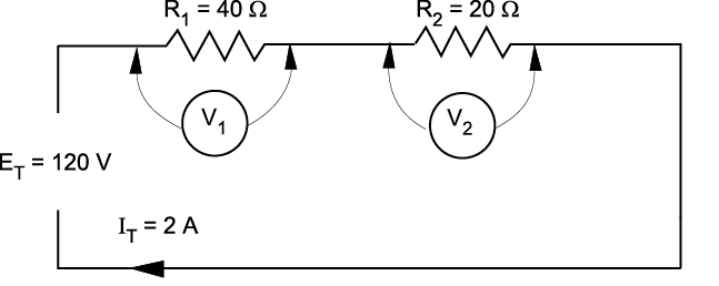
- Series circuit
From the values given above, you can easily calculate the voltage drop across each resistor by:
E1 = I1 × R1 = 2 A × 40 Ω = 80 V
E2 = I2 × R2 = 2 A × 20 Ω = 40 V
The voltage drop of 80 V across the 40 Ω resistor is twice the voltage drop across the 20 Ω resistor.
Refer to Figure 2. If an open is introduced between resistors R1 and R2 (for example, by disconnecting a lead), current flow through the circuit is, of course, interrupted. If there is no current flow, the voltage drop across each of the resistive elements is zero (since E = I × R).
However, the potential difference of the source still exists across the open. If a voltmeter is connected across the open, the reading is the same as if it were connected directly across the terminals of the supply source.
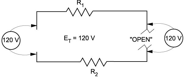
- Voltage across an open
In a series lighting circuit, you could easily determine which lamp was burnt open simply by measuring the voltage across the lamp-holder terminals, in succession, until you have measured the total source voltage.
 Caution! Since the source voltage still exists across the open in a series circuit, this represents a shock hazard. Be careful not to touch the live parts of the circuit!
Similarly, if a switch is opened, the full-source voltage will appear across the switch contacts. Even though the voltage across the load devices may be zero, if any of those loads are ahead of the switch they will be energized with full voltage to ground.
Troubleshooting series components
Sometimes you will be required to troubleshoot a piece of equipment that has stopped working. The first thing you would check for is power. Is the breaker off? Is the switch off? Is there a general power outage?
Once you have determined that power is still available you can begin using the multimeter to locate the problem. Starting with the first component or the one easiest to check, work your way through the circuit until you reach the component that shows no voltage reading. This is known as hopscotch voltage readings. Figure 3 illustrates this process. The dashed line indicates where the probe has already been placed and removed.
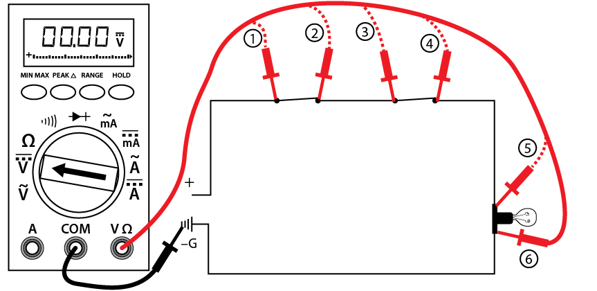
- Hopscotch troubleshooting
Follow these steps to complete the voltage test procedures with an autorange meter:
- Set the selector dial to the type of current to be tested: AC or DC.
- Once you have determined that the load (shown as a lightbulb) is not working, check for voltage across the light first to verify rule #2 (i.e., if you measure a correct voltage across a load and the load doesn’t work, the load has failed.).
- If you have voltage across the light, then the light has failed. If there are zero volts across the light, then one of the switches or wiring connections in the circuit has failed. If you have a zero reading across the light, continue with the next steps.
- Place the black probe at a grounded component.
- Place the red probe and check for a voltage reading at each test point in order starting at test point 1, verifying power supply.
- Continue working your way through the circuit until you get a zero reading, which would indicate a break in the circuit just before that point.
- Reading at 2 = switch #1 closed, zero at 2 = switch #1 open
- Reading at 3 = wiring to switch #2 good, zero at 3 = wiring to switch #2 open
- Reading at 4 = switch #2 closed, zero at 4 = switch #2 open
- Reading at 5 = wiring to light good, zero at 5 = wiring to light open
- Reading at 6 = load is energized, zero at 6 = the load is open (although you have already checked the load in your first test). If you get to this stage and the load is energized, the only component left that must be faulty is the final wiring from the load to ground.
- Once the open in the circuit has been identified, you can de-energize the circuit, remove the component, and double check the component with your ohmmeter.
- If this is the last test you are doing, turn the meter to “off” and store in a safe place.
Testing resistance (ohms) with a digital multimeter
This test, using a digital multimeter, determines whether:
- an electrical circuit is complete or broken
- the resistance of a component matches the manufacturer’s specification
Follow these steps to complete the resistance test procedure:
- Make sure all power is off on the circuit you are testing.
- Make sure that the component that you are testing is isolated from the complete circuit. Either remove the component from the circuit or isolate it with an open switch.
- Set the selector dial to Ω.
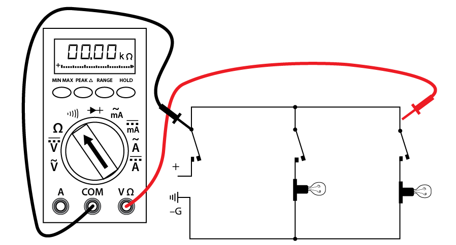
- Connect the test lead and probes to the component terminals as shown (Figure 4).
- Observe the readout window to obtain the Ω reading.
- Compare the results to the manufacturer’s Ω specifications. If the readings match the component, then resistance is not a problem.
- If the component is a load, there should be resistance that matches the manufacturer’s specs.
- If the reading is infinite (I) or overloaded (OL), then the component is open.
- If the reading is zero, then the component is closed (if it is a load then this is an internal short).
- If this is the last test you are doing, turn the meter to “off” and store it in a safe place.
- Ohm test of a load
 There may be other circuits that are energized even though the circuit you are working on is not energized. DO NOT TOUCH THE METER PROBES TO ANY ENERGIZED COMPONENTS WHEN TESTING FOR CONTINUITY. YOU MAY DAMAGE THE METER.
Continuity test
This is a quick audible alarm test using a digital multimeter to determine whether an electrical circuit or wire is complete or broken.
This test can be applied to a circuit as a whole or in sections—on individual components or sections of wiring. A break in continuity can be caused by mechanical damage, corrosion of components, or simply a switch being left open.
Follow these steps to complete the continuity test procedure with an autorange digital meter:
- Make sure all power is off in the circuit you are testing.
- Set the selector dial to Ω (audible alarm symbol).
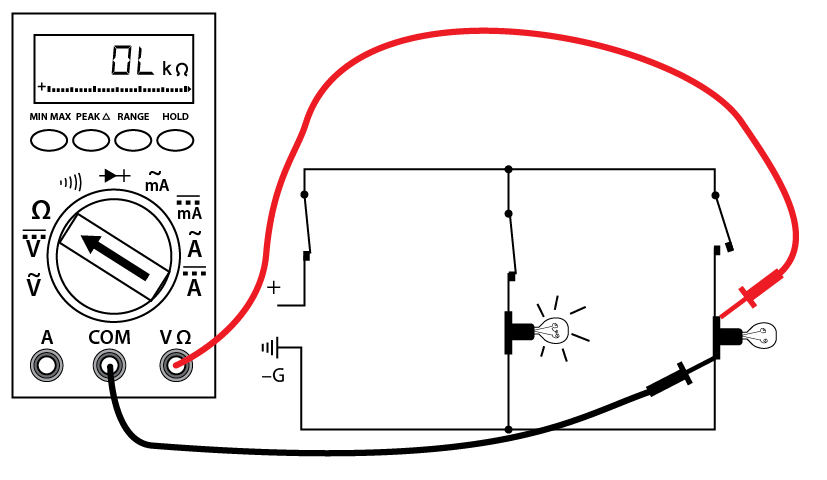
- Connect the test lead and probes on the load terminals as shown (Figure 5). The audible alarm will indicate continuity without a need for taking your eyes off the work.
- Touch the probes together to check the leads, connections, and battery life. The audible alarm should sound. With the leads apart the meter should display OL or I, depending on the manufacturer.
- If this is the last test you are doing, turn the meter to “off” and store it in a safe place.
- Wiring for a continuity test
Note: There may be other circuits that are energized even though the circuit you are working on is not energized. DO NOT TOUCH THE METER PROBES TO ANY ENERGIZED COMPONENTS WHEN TESTING FOR Ω (RESISTANCE). YOU MAY DAMAGE THE METER.
Polarity in a parallel circuit
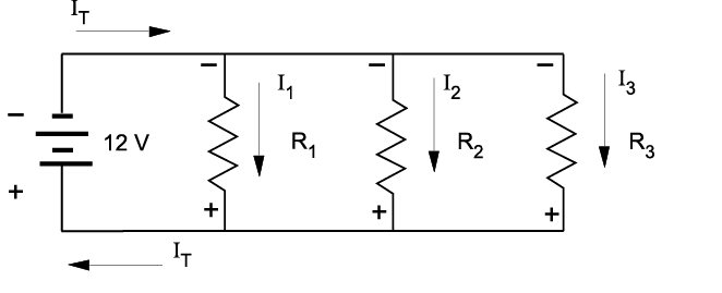
Just as in series circuits, electrical current flows “from negative to positive” through each of the load components in a parallel circuit. As illustrated in Figure 6, electrons leave the negative terminal of the source and flow from negative to positive through each of the load resistors. Note that the polarity of each of the resistors is the same as the polarity of the source.
6. Polarity test
-
- Tie one side of the power sources together.
- Before connecting the paralleling jumper between the remaining two terminals, insert a voltmeter between these two points. See Figure 7.
- If the polarity is incorrect (Figure 7b), the voltmeter indicates two times the source voltage, because the equal EMFs aid each other. Do NOT connect across these terminals.Polarity in a parallel circuit
Polarity is always expressed from one point of a circuit relative to another point with a different electrical potential. Note that in Figure 6 the top side of each resistor, which is marked negative, is in effect the same point. No difference in potential exists between any of these like terminals.
Also notice that the individual currents through each resistor (I1, I2, I3) together constitute the total current (IT) drawn from the source. When the total current required to operate each of these parallel loads exceeds the current output rating of the one source, you will need to increase the source output.
Polarity test for parallel voltage sources
Voltage sources are connected in parallel whenever it is necessary to deliver a current output greater than the current output a single source of supply can provide, without increasing voltage across a load.
- Power sources are connected in series to increase the voltage output.
- Conversely, power sources are connected in parallel to increase the current capacity.
An advantage of parallel-connected power sources is that one source can be removed for maintenance or repairs while reduced power to the load is maintained. If a 6 V battery has a maximum current output of 1 A, and if it is necessary to supply a load requiring 2 A, then you can connect a second 6 V battery in parallel with the first.
If there is any doubt about the polarity of the two batteries, then you can do a simple voltmeter test for correct polarity.